Device and method for suppressing intensity noise in optical signal

An intensity noise and optical signal technology, applied in the field of optical signal processing, can solve the problems of suppressing device failure, system instability, poor optical signal processing ability, etc., and achieve the effects of stable working state, improved performance, and improved accuracy

Inactive Publication Date: 2011-12-07
BEIHANG UNIV
View PDF8 Cites 22 Cited by
  • Summary
  • Abstract
  • Description
  • Claims
  • Application Information

AI Technical Summary

Problems solved by technology

[0007] The operating point of the intensity modulator is easily affected by changes in environmental factors such as ambient temperature, humidity, and electromagnetic fields. The drift of the operating point of the intensity modulator will directly lead to a decline in the suppression effect of the intensity modulator on the intensity noise of the optical signal, and even make the entire The suppression device fails, so that the fiber optic gyroscope cannot work normally. This scheme does not consider the influence of the drift of the working point of the intensity modulator on the suppression effect of the intensity noise
This solution uses analog closed-loop control technology, which has the problems of poor optical signal processing capability and system instability.

Method used


Image

  • Device and method for suppressing intensity noise in optical signal
  • Device and method for suppressing intensity noise in optical signal
  • Device and method for suppressing intensity noise in optical signal

Examples


Embodiment 1

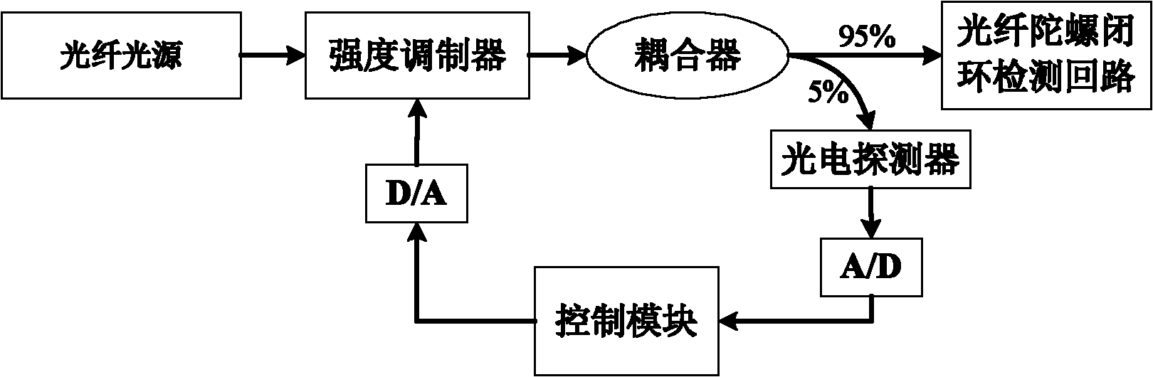
[0030] The schematic diagram of the structure of an intensity noise suppression device based on square wave modulation tracking the operating point of the intensity modulator provided by this solution is as follows: figure 2 As shown, the above suppression device mainly includes: an optical fiber light source, an intensity modulator, a coupler, a photodetector, an A / D (analog to digital) conversion module, a control module, and a D / A (digital to analog) conversion module. The functions of each module in the above suppression device are introduced below.

[0031] The optical fiber light source is used to send out light signals through the light source drive circuit. The optical fiber power source can be a super fluorescent optical fiber light source, which is a wide-spectrum light source.

[0032] The intensity modulator is placed between the optical fiber light source and the coupler to receive the optical signal emitted by the optical fiber light source, and modulate the power of ...

Embodiment 2

[0078] based on figure 2 The suppression device shown in this embodiment provides a method for suppressing intensity noise in an optical signal. The processing flow is as follows: Picture 9 As shown, including the following processing steps:

[0079] Step 91: The photodetector samples the light signal output by the intensity modulator after intensity noise suppression to obtain a voltage signal, and the A / D conversion module converts the voltage signal into a digital signal, and outputs the digital signal to the Control module realized by digital circuit.

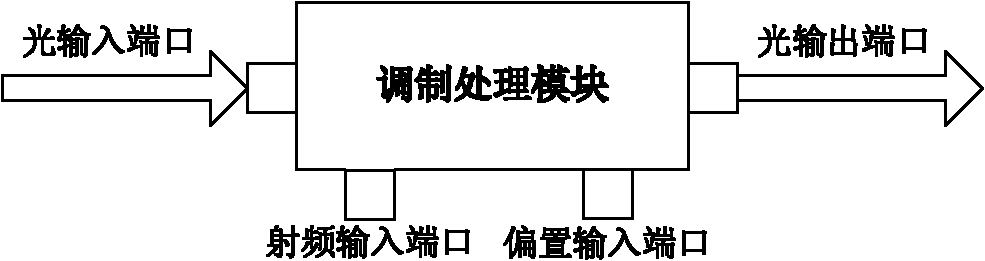
[0080] The optical fiber light source emits a light signal through the light source driving circuit, and the optical fiber power source can be a super-fluorescent optical fiber light source in an optical fiber gyroscope, which is a wide-spectrum light source. The optical input port in the intensity modulator receives the optical signal from the optical fiber light source, and suppresses the intensity noise of the optical signa...


PUM


Abstract

An embodiment of the invention provides an apparatus and a method for inhibiting intensity noise in an optical signal. The method comprises the following steps of: carrying out sampling on an optical signal output by an intensity modulator to obtain a voltage signal; demodulating the voltage signal; and generating a control signal according to a demodulation result. The control signal includes a power control signal for adjusting power of the optical signal and a modulating square wave signal for adjusting a working point of the intensity modulator. The intensity modulator modulates the powerof the received optical signal according to the received power control signal in the control signal, and adjusts the working point of the intensity modulator according to the received modulating square wave signal in the control signal, so as to maintain the working point of the intensity modulator stable. The embodiment of the invention can realize effective inhibition of the intensity noise in the optical signal while ensuring the working point of the intensity modulator stable.

Description

Technical field [0001] The present invention relates to the technical field of optical signal processing, in particular to a device and method for suppressing intensity noise in an optical signal. Background technique [0002] As a new type of inertial angular velocity sensor with extremely rapid development, fiber optic gyroscope has the advantages of no moving parts and no errors caused by acceleration. It has become the main inertial device in more and more fields and has become the main research direction in the next generation of aviation. . However, an important difference between the fiber optic gyroscope and the traditional electromechanical gyroscope is that there is a large amount of noise, which mainly includes the noise of the broad-spectrum light source of the fiber optic gyroscope. [0003] The noise of the fiber optic gyroscope will directly affect the performance indicators of the fiber optic gyroscope's random walk coefficient and zero bias instability, and direct...

Claims


Application Information

Patent Timeline
Patent Type & Authority Applications(China)
IPC IPC(8): G01C19/72
Inventor 许文渊张春熹于海鹏李立京张晞李慧
Owner BEIHANG UNIV
Why Eureka
Try Eureka