
Gas flow meter and throttling device used therein, ventilator, anesthesia machine

A gas flow meter and throttling device technology, applied in the field of sensors, can solve the problems of large exhalation resistance, small flow measurement range, small pressure difference change, etc., to meet the requirements of measurement accuracy, large flow detection range, and increased resistance Effect

Active Publication Date: 2011-12-07
BEIJING AEONMED
View PDF7 Cites 13 Cited by
  • Summary
  • Abstract
  • Description
  • Claims
  • Application Information

AI Technical Summary

Problems solved by technology

However, in the medical clinical field, such as the gas flow measurement of ventilator, anesthesia machine, etc., this kind of flowmeter has obvious disadvantages: that is, if the orifice diameter of the throttling device in the flowmeter is small, the flow measurement range will be relatively narrow. If the diameter of the orifice of the throttling device in the flowmeter is set to be larger, it may meet the requirements of the measurement range, but due to the small The pressure difference change in the flow range is too small to achieve accurate measurement
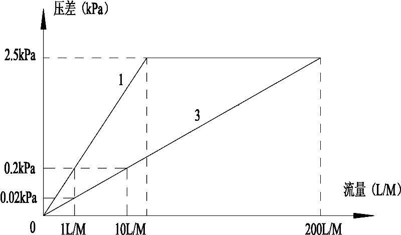
Specifically, such as figure 1 As shown, curve 1 is the pressure difference-flow relationship curve when the orifice diameter of the throttling device of the flowmeter in a ventilator is set to a small value. It can be seen from the figure that when the flow rate increases, the gas The passing resistance increases rapidly, and soon reaches the full scale of the differential pressure flow sensing device, which cannot meet the maximum flow measurement requirements of the ventilator, and also causes excessive expiratory resistance, affecting the therapeutic effect of the ventilator and patient comfort.
Curve 3 is the pressure difference-flow relationship curve when the orifice of the throttling device is set to a larger value. It can be seen from the figure that this curve meets the requirements of the flow measurement range, but the pressure difference change in the small flow range is too small , the differential pressure flow sensor device cannot accurately reflect the flow change, and cannot meet the accuracy measurement requirements
Therefore, the throttling device used in the flowmeter in the prior art cannot simultaneously ensure that the flowmeter can detect the flow well when the measured gas is a small flow rate and a large flow rate

Method used


Image

  • Gas flow meter and throttling device used therein, ventilator, anesthesia machine
  • Gas flow meter and throttling device used therein, ventilator, anesthesia machine
  • Gas flow meter and throttling device used therein, ventilator, anesthesia machine

Examples


Embodiment Construction

[0025] The embodiments of the present invention will be described in detail below with reference to the accompanying drawings, but the present invention can be implemented in many different ways defined and covered by the claims.

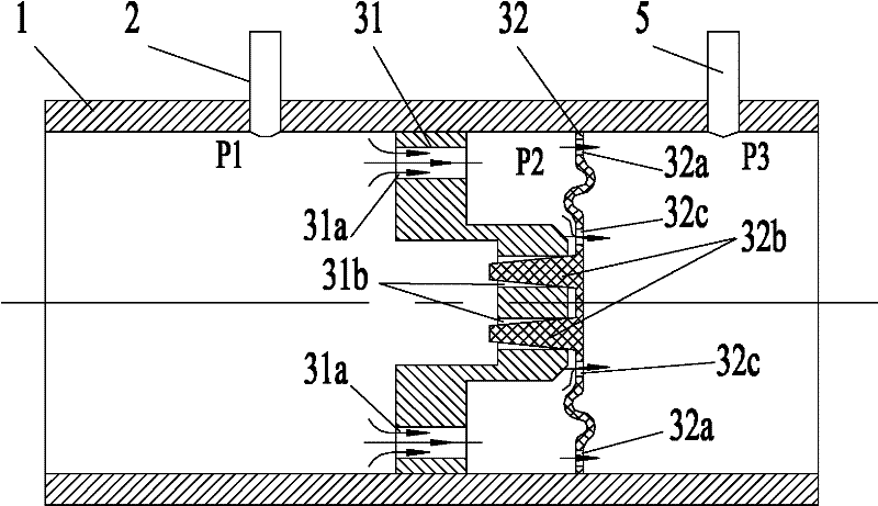
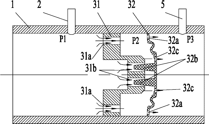
[0026] Such as figure 2 and image 3 As shown, the throttling device 3 used in the gas flow meter according to the first embodiment of the present invention is arranged in the pipeline through which the gas flows. The arrows in the figure indicate the flow direction of the gas in the pipeline. As can be seen from the figure, the throttling device 3 is provided with a throttling hole, and the cross-sectional area of ​​the throttling hole is smaller than the cross-sectional area of ​​the pipeline through which the gas flows. The cross-sectional area of ​​the orifice is designed to increase as the gas flow rate reaching the throttling device 3 increases. image 3 The gas flow in the pipeline is greater than figure 2 The gas flow in the pipeline i...


PUM


Abstract

The invention discloses a gas flowmeter and a throttling device used therein, a breathing machine and an anaesthesia machine. The throttling device is arranged in a pipeline through which gas flows, and is provided with throttling holes; and the sectional area of each throttling hole is smaller than that of the pipeline through which the gas flows and is increased with the increase of the flow ofthe gas reaching the throttling device (3). The throttling device ensures that the gas flowmeter provides an enough measurement range and meets measurement accuracy, and the gas flowing resistance cannot be obviously increased when the flow of the gas is large.

Description

technical field [0001] The invention relates to the field of sensors, in particular to a gas flowmeter and a throttling device used therein, a ventilator provided with the gas flowmeter, and an anesthesia machine provided with the gas flowmeter. Background technique [0002] During the use of medical devices such as ventilators and anesthesia machines, patients need to be mechanically ventilated. For patients, especially infants and critically ill patients, the control of the ventilation volume and the resistance of the exhalation end are very important. . Improper ventilation can be dangerous for the patient. Therefore, the control of the ventilation flow is very important, and it is necessary to accurately measure the flow of the ventilation flow. [0003] Among the gas flowmeters used in existing ventilators and anesthesia machines, there is an orifice-type flowmeter, which is composed of a throttling device, a sampling pipeline and a differential pressure flow sensor d...

Claims


Application Information

Patent Timeline
IPC IPC(8): G01F1/36G01F1/40A61M16/00A61M16/01
Inventor 王军
Owner BEIJING AEONMED
Learn More