Device and method for testing polarization extinction ratio of polarization maintaining fiber coupler based on resonant cavity technology

A technology of polarization extinction ratio and polarization maintaining optical fiber, which is applied in the direction of testing optical performance, etc., and can solve the problems of affecting test accuracy, expensive test instruments, and large environmental dependence

Inactive Publication Date: 2011-12-07
ZHEJIANG UNIV
View PDF4 Cites 12 Cited by
  • Summary
  • Abstract
  • Description
  • Claims
  • Application Information

AI Technical Summary

Problems solved by technology

If the polarization extinction ratio is too low, the output signal will be weakened and the test accuracy will be affected
[0003] Commonly used methods for

Method used


Image

  • Device and method for testing polarization extinction ratio of polarization maintaining fiber coupler based on resonant cavity technology
  • Device and method for testing polarization extinction ratio of polarization maintaining fiber coupler based on resonant cavity technology
  • Device and method for testing polarization extinction ratio of polarization maintaining fiber coupler based on resonant cavity technology

Examples


Embodiment Construction

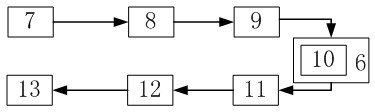
[0019] like figure 1 , 3 As shown, the device for testing the polarization extinction ratio of a polarization maintaining fiber coupler based on resonant cavity technology includes a temperature control panel 6, a fiber laser 7, a first isolator 8, a 15° fusion splice point 9, a fiber ring resonant cavity 10, and a second isolator 11 , photodetector 12 and oscilloscope 13; fiber laser 7, first isolator 8, 15 ° splice point 9, fiber ring resonator 10, second isolator 11, photodetector 12 and oscilloscope 13 are connected in sequence; fiber ring The resonant cavity 10 is placed on the temperature control panel 6 .

[0020] The steps of the method for testing the polarization extinction ratio of a polarization maintaining fiber coupler based on resonant cavity technology are as follows:

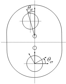
[0021] 1) The second input port 3 and the second output port 4 of the polarization-maintaining fiber coupler pass through the 0° fusion point 5 to form a fiber ring resonator 10, and as for t...


PUM


Abstract

The invention discloses a device and method for testing polarization extinction ratio of a polarization-maintaining fiber coupler based on resonator technology. One output end and one input end of the polarization-maintaining fiber coupler are connected to form a fundamental annular resonator structure; a polarization axis alignment angle error of the polarization-maintaining fiber coupler is obtained by testing a resonance curve of an optical fiber annular resonator so as to obtain the polarization extinction ratio of the polarization-maintaining fiber coupler. The device for testing polarization extinction ratio of the polarization-maintaining fiber coupler comprises an optical fiber laser, a first isolator, an optical fiber annular resonator, a second isolator, a photoelectric detectorand an oscillograph which are connected in order; and the optical fiber annular resonator is arranged on a temperature-controlled panel. For an in separable optical waveguide resonator of the opticalfiber coupler, the device and method provided by the invention can test the polarization extinction ratio of the coupler constituting the resonator in non-destructive manner. The invention provides anovel and simple method for testing polarization extinction ratio of the polarization-maintaining fiber coupler with important scientific significance and application value.

Description

technical field [0001] The invention relates to a device and method for testing the polarization extinction ratio of a polarization-maintaining fiber coupler based on a resonant cavity technology. Background technique [0002] The polarization-maintaining fiber coupler is a coupler that can keep the coupled light in the same polarization state as the input linearly polarized light. It is a key device for various interferometric sensors and coherent communication, and it is also one of the basic components that constitute a high-precision, high-performance fiber optic gyroscope. . In the fiber optic gyroscope, the polarization maintaining fiber coupler is an important device connecting the light source, photodetector and fiber resonator. On the one hand, the polarization-maintaining fiber coupler inputs the light wave of the light source into the fiber ring, and on the other hand outputs the light intensity with angular rate information to the detector. In the optical waveg...

Claims


Application Information

Patent Timeline
IPC IPC(8): G01M11/02
Inventor 马慧莲姚灵芝金仲和
Owner ZHEJIANG UNIV
Why Eureka
Try Eureka