
Fuel cell system including heat exchanger

A fuel cell system and fuel cell technology, applied in the direction of fuel cells, fuel cell additives, fuel cell components, etc., can solve the problems of increasing the cost of fuel cell systems

Active Publication Date: 2011-12-07
BELENOS CLEAN POWER HLDG
View PDF5 Cites 7 Cited by
  • Summary
  • Abstract
  • Description
  • Claims
  • Application Information

AI Technical Summary

Problems solved by technology

The presence of thermal insulation also increases the cost of manufacturing fuel cell systems

Method used


Image

  • Fuel cell system including heat exchanger
  • Fuel cell system including heat exchanger
  • Fuel cell system including heat exchanger

Examples


Embodiment Construction

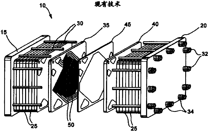
[0016] figure 1 The prior art proton exchange membrane fuel cell stack 10 is shown in an exploded view. The stack 10 includes a pair of end plate assemblies 15 and 20 and a plurality of fuel cell assemblies 25. In this particular example, an electrically insulating tie rod 30 extends between the end plate assemblies 15, 20 to hold and fix the stack assembly 10 in its assembled state by means of a fastening nut 32. A spring 34 interposed between the fastening nut 32 and the end plate 20 pierced on the tie rod 30 applies an elastic compression force to the stack 10 in the longitudinal direction. Reactant and coolant fluid streams are provided to internal manifolds and passages in the stack 10 through inlets (not shown) in the end plate 15 and discharged from outlets (not shown).

[0017] Each fuel cell assembly 25 includes an anode flow field plate 35, a cathode flow field plate 40, and an MEA 45 interposed between the plates 35 and 40. The anode and cathode flow field plates 35 ...


PUM


Abstract

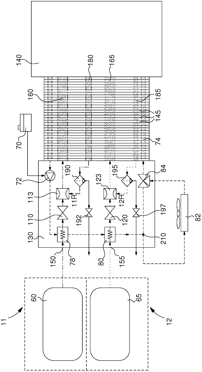
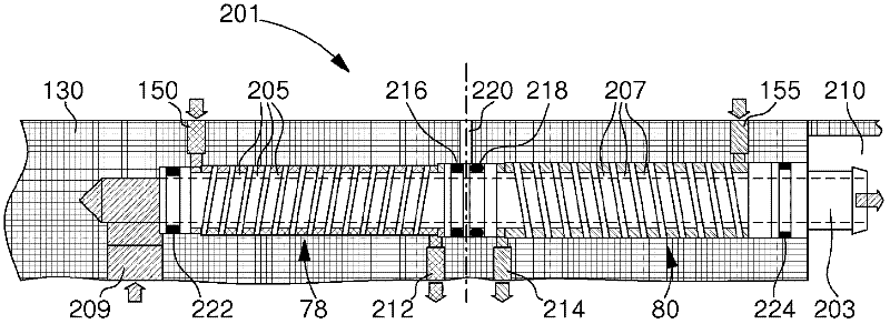
A fuel cell system including: a fuel cell stack including plural fuel cells sandwiched between two end plates; a fuel supply system supplying a stream of fuel gas to the fuel cell stack; an oxidizer supply system supplying a stream of oxidizer gas to the fuel cell stack; a closed loop coolant circulation system driving a cooling liquid through the fuel cell stack so that the cooling liquid enters the fuel cell stack, absorbs heat from the fuel cells, and exits the fuel cell stack. The coolant circulation system includes a circulation pump driving the cooling liquid, a heat exchanger removing heat from the cooling liquid and for at least partially transferring the heat to the stream of fuel gas and / or the stream of oxidizer gas. The heat exchanger includes a tube made from a heat-conducting material and inserted into a bore in one of the end plates, the tube and the bore defining at least a first fluid channel inside the tube and a second fluid channel in a space existing between the tube and the sides of the bore in the end plate, one of the first and second fluid channels being for the cooling liquid, and the other fluid channel being for the fuel or the oxidizer gas.

Description

Technical field [0001] The present invention generally relates to fuel cell systems in which heat from a cooling liquid is used to preheat the reactant gas before it is supplied to the fuel cell. Background technique [0002] Electrochemical fuel cells convert fluid reactants (ie, fuel and oxidant streams) into electricity, heat, and reaction products. Fuel cells generally include an electrolyte arranged between two porous conductive electrode layers. In order to cause the desired electrochemical reaction, both the anode and the cathode may include one or more catalysts. [0003] At the anode, the fuel moves through the porous electrode layer and is oxidized by the catalyst to simultaneously generate cations (usually protons) and electrons. The cations migrate toward the cathode through the electrolyte. The oxidant (usually pure oxygen or an oxygen-containing mixture) moves through the porous cathode and reacts with cations from the anode that pass through the membrane. In the ...

Claims


Application Information

Patent Timeline
Patent Type & Authority Applications(China)
IPC IPC(8): H01M8/02H01M8/04
CPCH01M8/0267Y02E60/50H01M8/04089H01M8/04074H01M8/04201H01M8/04029H01M8/2484H01M8/241H01M8/2457H01M8/0258
Inventor U·汉内森A·特斯卡达
Owner BELENOS CLEAN POWER HLDG
Learn More