
Photovoltaic power plant with a compensated voltage source controlling the dc potential at the output of the converter

一种光伏发电站、补偿电压源的技术,应用在光伏发电站领域,能够解决耗费劳力、不希望电压接地回路电流等问题

Active Publication Date: 2011-12-07
SMA SOLAR TECH AG
View PDF4 Cites 116 Cited by
  • Summary
  • Abstract
  • Description
  • Claims
  • Application Information

AI Technical Summary

Problems solved by technology

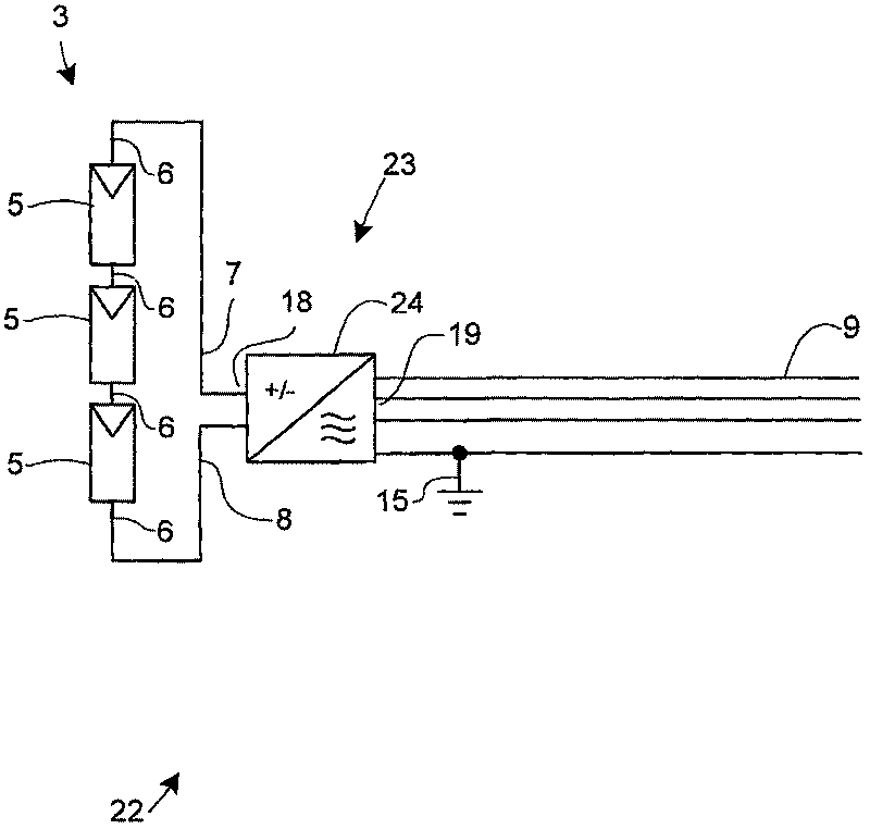
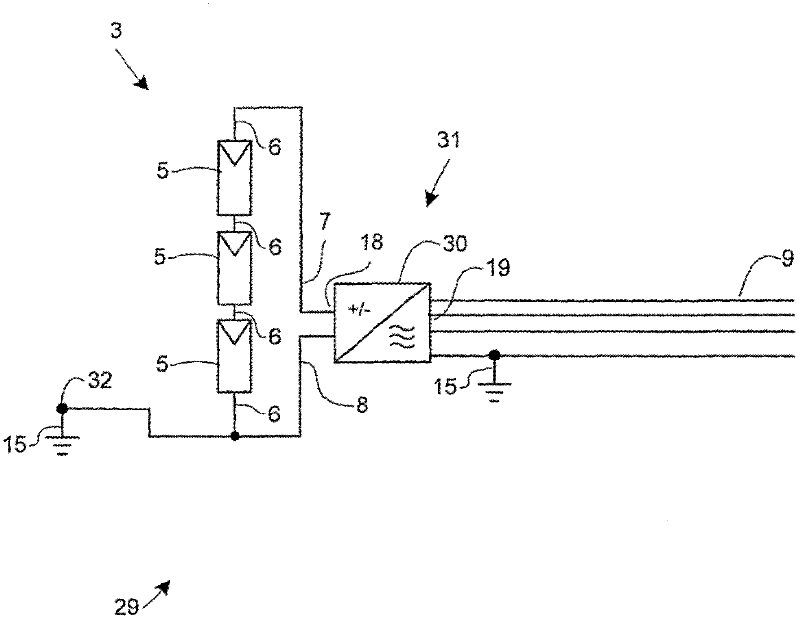
[0014] A disadvantage of this type of power station is the requirement that the ground connection 32 needs to be physically connected to either the positive input 7 or the negative input 8 of the converter 24
This requires additional assembly labor and hardware
Furthermore, changing PV module types at a later date may involve physical disconnection and / or reconnection of ground connection 32, a labor-intensive process and thus a disadvantage
Additionally, if Image 6 If two or more PV generators 23 are shown connected in parallel, and one input of each inverter 23 is grounded as described above, problems can arise if the characteristics or irradiance of each PV string 3 are not the same
This can lead to unwanted voltages and consequent ground loop currents
[0015] In all the prior art power plants described above, it can be seen that although the potential of one or more PV strings with respect to ground is an important parameter for operating the power plant in an efficient manner and does not lead to damage, but this is often only achievable with expensive hardware or laborious assembly of additional hardware

Method used


Image

  • Photovoltaic power plant with a compensated voltage source controlling the dc potential at the output of the converter
  • Photovoltaic power plant with a compensated voltage source controlling the dc potential at the output of the converter
  • Photovoltaic power plant with a compensated voltage source controlling the dc potential at the output of the converter

Examples


Embodiment Construction

[0051] Figure 7 The PV power station 34 includes a PV generator 2 including a PV string 3 and a converter 4 . The converter 4 has a DC input 18 and a three-phase AC output 19 . The converter 4 includes a balancing circuit such that the DC potential at the DC input 18 of the converter 4 is symmetrical around the average DC potential at the AC output 19 thereof. In its simplest form, a balancing circuit may comprise a voltage divider based on resistors, inductors and / or capacitors. The PV string 3 comprises three PV modules 5 connected in series and configured such that they will be exposed to sunlight. Each PV module 5 includes several PV cells (not shown) connected as known in the art so that they produce a single DC power output at terminals 6 of the PV module 5 . The PV string 3 is electrically connected to the DC input 18 of the converter 4 via a positive connection 7 and a negative connection 8 . The AC output 19 is electrically paralleled to the grid 9 via a three-ph...


PUM


Abstract

In large PV power plants, grounding of individual PV modules may lead to problems. The present invention overcomes such problems. The PV power plant (34) comprises an offset voltage source (14), wich controls the DC potential at the AC outputs (19). Thereby, the DC potential at the DC input will be indirectly controlled, and it is thus possible to ensure that the potentials with respect to ground (15) at the terminals of PV modules (5) are all non-negative or all non-positive without grounding the PV modules. Ground loops can be avoided, and there is no need for the use of transformer-based inverters (4).

Description

technical field [0001] The present invention relates to a photovoltaic (PV) power plant. Background technique [0002] In larger PV power plants with DC / AC converters (converters), the power plant is typically connected to the grid via a dedicated isolation transformer that connects the lower voltage PV generator system to the medium voltage grid. One of the reasons for this is that PV modules that convert solar energy into electricity generally must have a defined potential with respect to ground. This is generally accomplished by grounding all or some of the PV modules. [0003] Grounding is usually done to comply with local regulations, to detect insulation defects of the PV modules, and / or to avoid corrosion and / or yield reduction of the PV modules. [0004] In larger systems, it may be difficult to detect insulation defects because of the considerable leakage currents of individual PV modules, especially under wet conditions. Leakage current can be monitored by grou...

Claims


Application Information

Patent Timeline
Patent Type & Authority Applications(China)
IPC IPC(8): H02J3/38
CPCH02J3/383H02M7/48Y02E10/563H02J2300/24H02J3/381Y02E10/56H02J3/46H02J3/38H02J7/35
Inventor 乌非.博拉普弗里克.哈斯
Owner SMA SOLAR TECH AG
Learn More