
Suspension device for mining vehicles

A suspension device, mining vehicle technology, applied in the direction of suspension, elastic suspension, vehicle parts, etc., can solve the problems of harsh working conditions, reduced quality and reliability of the whole vehicle, insufficient manufacturing process, etc., to reduce wear, improve Vehicle reliability and the effect of improving vehicle carrying capacity

Inactive Publication Date: 2011-12-14
SINO TRUK JINAN POWER
View PDF5 Cites 5 Cited by
  • Summary
  • Abstract
  • Description
  • Claims
  • Application Information

AI Technical Summary

Problems solved by technology

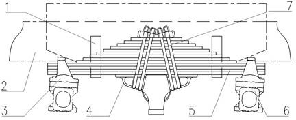
Due to the special working environment of the mining vehicle, the load is large and the working conditions are harsh. Therefore, during use, the rear axle leaf spring 3 limit block and the leaf spring 3 front and rear brackets are abnormally worn, and the end cover of the balance shaft 4 is cracked, and the plate Faults such as single-piece breakage of spring 3 and breakage of saddle bolt 7 lead to a high failure rate of the suspension device and a decrease in the quality and reliability of the vehicle
However, due to the limitations of the current leaf spring structure design and insufficient manufacturing process, it is difficult to increase the sufficient load-bearing capacity to meet the requirements for the suspension device of large mining vehicles.

Method used


Image

  • Suspension device for mining vehicles
  • Suspension device for mining vehicles
  • Suspension device for mining vehicles

Examples


Embodiment Construction

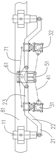
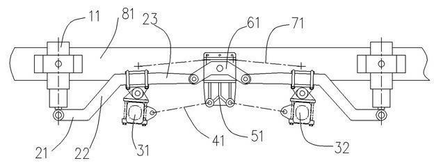
[0031] Such as figure 2 As shown, a suspension device for a mining vehicle is mainly composed of a balance arm 61, an oil-pneumatic spring 11, an elastic beam, a balance bracket 51, an upper thrust rod 71, a lower thrust rod 41 and a lateral thrust rod (not shown in the figure). , oil and gas spring 11, elastic beam, upper thrust rod 71, lower thrust rod 41 and lateral thrust rod are two.

[0032] in:

[0033] The balance arm 61 is V-shaped, and its spine is hinged on the vehicle frame 81 between the double rear axles (rear axle I 31 and rear axle II 32 shown in the figure). Preferably, the balance arm 61 is arranged in an inverted V shape. Preferably, the distance between the hinge point and the double rear axle is approximately equal.

[0034] The two oil-pneumatic springs 11 are respectively located outside the double rear axles. In other words, the double rear axles are located between the two oil-pneumatic springs 11 , and the outer cylinders of the oil-pneumatic spr...


PUM


Abstract

The invention discloses a suspension system for mine trucks, which comprises a balance arm, two oil-gas springs, two elastic beams, a balance bracket, two upper thrusting rods, two lower thrusting rods and two transverse thrusting rods, wherein the balance arm is a V-shaped arm, and a ridged part of the balance arm is hinged with a frame arranged between two rear axles; the two rear axles are arranged between the two oil-gas springs, and an external cylinder tube of the oil-gas spring is fixedly connected with the frame; the two elastic beams are respectively arranged at the two sides of the balance arm; the balance bracket is fixed on the frame between the two rear axles; the two upper thrusting rods are respectively arranged at the two sides of the balance bracket, and the two ends of each upper thrusting rod are respectively hinged with the second straight section of the elastic beam on the same side of the upper thrusting rod and the upper part of the balance bracket; the two lower thrusting rods are respectively arranged at the two sides of the balance bracket, and the two ends of each lower thrusting rod are respectively hinged with an axle on the same side of the lower thrusting rod and the lower part of the balance bracket; and the two transverse thrusting rods extend along the direction of the axle, and the two ends of each transverse thrusting rod are respectively hinged between the frame and an axle bracket. By using the suspension system disclosed by the invention, the truck reliability is improved.

Description

technical field [0001] The invention relates to a suspension device, in particular to a suspension device suitable for mining vehicles with a weight below 100t. Background technique [0002] At present, mining vehicles with a total weight of less than 100t generally use the balanced suspension device of ordinary heavy-duty vehicles. like figure 1 As shown, the balance suspension device of this common heavy-duty vehicle mainly has to be made of leaf spring 5, leaf spring seat 3, saddle bolt 7 and limit block 1. The leaf spring 3 is formed by fastening a group of stacked leaf springs through saddle bolts 7, elastically connects the vehicle frame 2 and the axle 6, and bears the vertical load. The balance suspension device of this ordinary heavy-duty vehicle is directly applied on the mining vehicle after a slightly improved design. Due to the special working environment of the mining vehicle, the load is large and the working conditions are harsh. Therefore, during use, the ...

Claims


Application Information

Patent Timeline
IPC IPC(8): B60G11/26B60G21/045
Inventor 匡西友
Owner SINO TRUK JINAN POWER
Learn More