Design method of improved scram combustion chamber and its swirler

A technology of scramjet combustion chamber and combustion chamber, which is applied in mechanical equipment, ramjet engines, etc., can solve the problems of increasing engine mass load, reducing thrust-to-weight ratio of scramjet engine, and large total pressure loss, and reducing the weight of the engine. , the effect of improving combustion efficiency and increasing thrust-to-weight ratio

Inactive Publication Date: 2011-12-14
NANJING UNIV OF AERONAUTICS & ASTRONAUTICS
View PDF8 Cites 14 Cited by
  • Summary
  • Abstract
  • Description
  • Claims
  • Application Information

AI Technical Summary

Problems solved by technology

However, in the existing supersonic combustion chamber, it is difficult to mix oil and gas and the flame is difficult to stabilize, and the total pressure recovery coefficient and combustion efficiency of the combustion chamber are low, resulting in unsatisfactory working performance of the supersonic combustion chamber
In addition, when the airflow burns in the super-combustion chamber, it will generate a higher pulsating pressure, and this pulsating pressure will continue to propagate upstream through the boundary layer of the co...

Method used


Image

  • Design method of improved scram combustion chamber and its swirler
  • Design method of improved scram combustion chamber and its swirler
  • Design method of improved scram combustion chamber and its swirler

Examples


Embodiment Construction

[0024] In order to enable the public to fully understand the technical essence and beneficial effects of the present invention, the applicant will describe in detail the specific implementation of the present invention below in conjunction with the accompanying drawings, but the applicant's description of the embodiments is not a limitation to the technical solution. Changes in the form of the inventive concept rather than in substance should be regarded as the protection scope of the present invention.

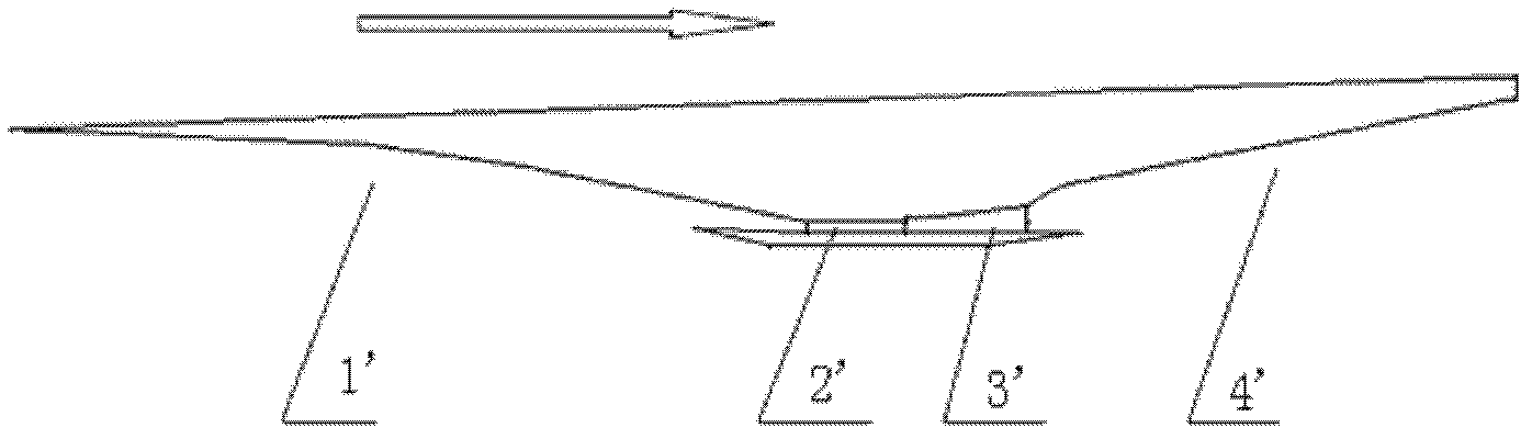
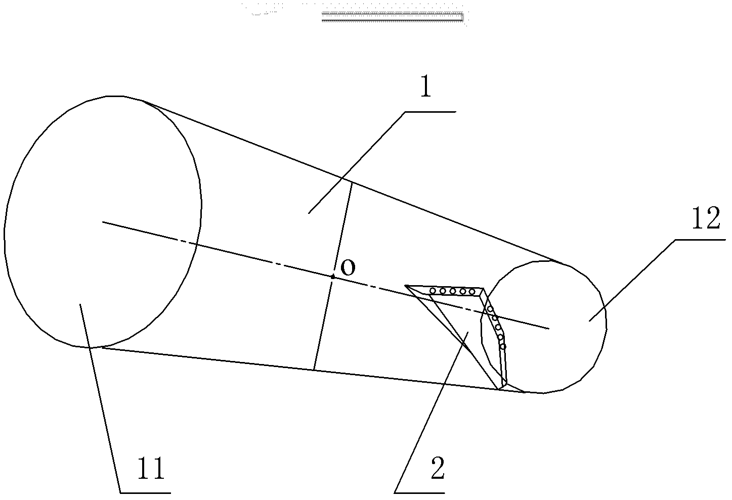
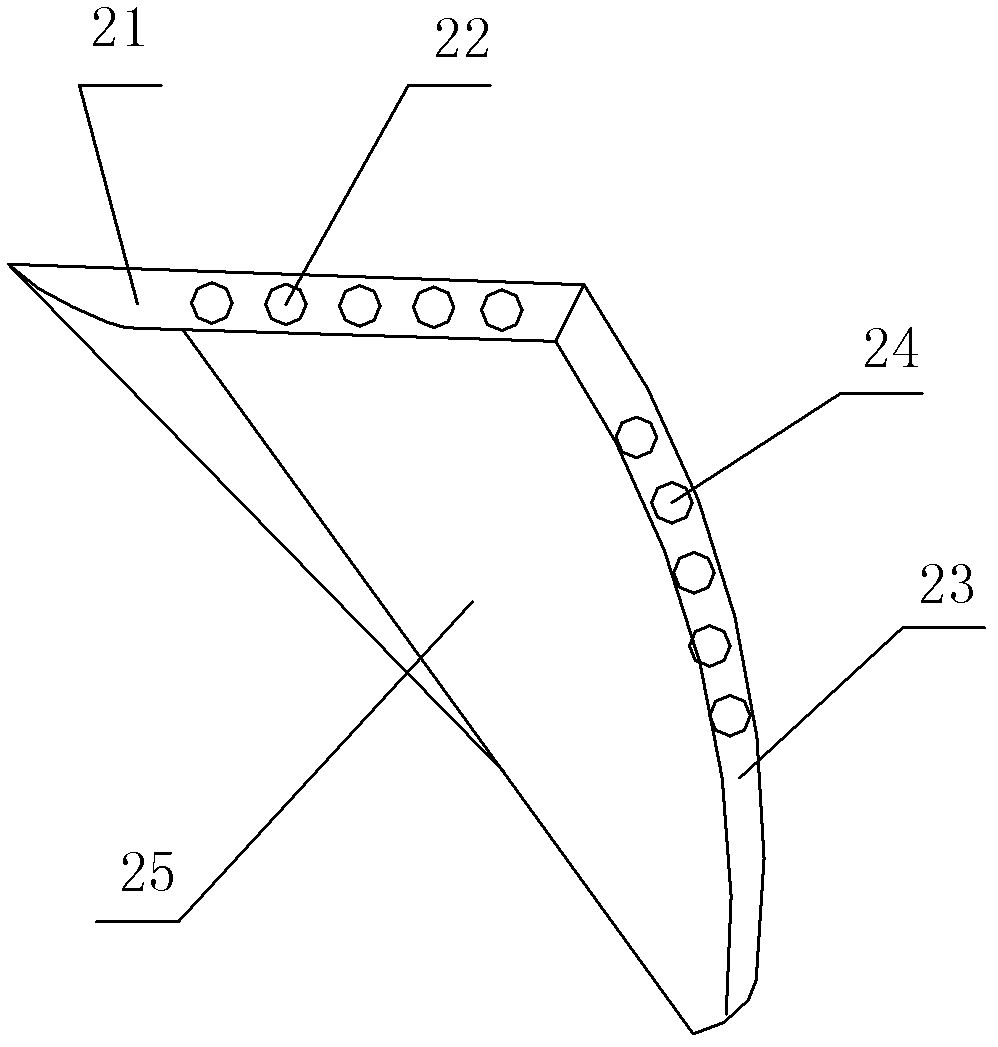
[0025] Such as Figures 2 to 5 As shown, the improved super-combustion combustion chamber of the present invention includes a combustion chamber 1, the cross section of the inner flow channel of the combustion chamber 1 is circular or elliptical, and a device that causes air flow is installed near the inlet of the inner flow channel of the combustion chamber 1. The swirler 2 that spirally moves; the swirler 2 includes a swirl generating upper wall plate 26 that makes the air ...


PUM


Abstract

The invention discloses a modified scramjet combustion chamber and a design method of a swirler thereof. The swirler capable of causing air flow to generate helical motion is arranged in a combustion chamber and comprises a rotational flow generation upper wallboard, a rotational flow generation lower wallboard, a back end surface wallboard and a sidewall mounting surface, wherein the rotational flow generation upper wallboard is used for making the air flow entering the combustion chamber generate oblique shock waves, and the rotational flow generation lower wallboard is used for making the air flow entering the combustion chamber generate expansion waves. The sidewall mounting surface is connected with the combustion chamber, and the front edge of the swirler faces to an inlet of the combustion chamber; the back end surface wallboard is arranged opposite to an outlet of the combustion chamber; the interior of the swirler is provided with a fuel conveying embedded pipe; an inlet of the fuel conveying embedded pipe is arranged on the sidewall mounting surface; and an injection opening of the fuel conveying embedded pipe is arranged at the back end surface wallboard. Therefore, the invention has the advantages of improving the mixing efficiency and the combustion efficiency of the fuel of a scramjet, shortening the lengths of an engine isolating section and the combustion chamber, further optimizing the structure of the engine, increasing the thrust-weight ratio of the engine and improving the whole performances of the engine.

Description

technical field [0001] The invention relates to a scramjet combustion chamber, which is mainly used in a scramjet engine. Background technique [0002] At present, common scramjet inner runners, such as figure 1 As shown, it mainly includes an intake port 1', an isolation section 2', a combustion chamber' and a nozzle 4' connected in sequence. [0003] Supercombustion chambers are mainly used to achieve uniform mixing and full combustion of oil and gas in supersonic airflows. They have huge development potential and are increasingly valued and concerned by various countries. However, in the existing supersonic combustion chamber, it is difficult to mix oil and gas and the flame is difficult to stabilize, and the total pressure recovery coefficient and combustion efficiency of the combustion chamber are low, which leads to unsatisfactory working performance of the supersonic combustion chamber. In addition, when the airflow burns in the super-combustion chamber, it will gen...

Claims


Application Information

Patent Timeline
IPC IPC(8): F02K7/10
Inventor 顾瑞徐惊雷张堃元莫建伟刘凯礼
Owner NANJING UNIV OF AERONAUTICS & ASTRONAUTICS
Why Eureka
Try Eureka