led light board

A technology of LED lamp board and LED chip, which is applied to lighting devices, cooling/heating devices of lighting devices, light sources, etc., can solve the problems of poor heat dissipation of high-power LED lamps, excessive light decay of light exiting medium, serious problems, etc. Improve light utilization, improve life, and reduce light loss

Active Publication Date: 2011-12-14
HANGZHOU HIKVISION DIGITAL TECH
View PDF5 Cites 1 Cited by
  • Summary
  • Abstract
  • Description
  • Claims
  • Application Information

AI Technical Summary

Problems solved by technology

[0006] The purpose of the present invention is to provide an LED lamp board, which solves the problems of poor heat dissipation of current high-power LED lamps and serious light attenuation caused by excessive light emission medium.

Method used


Image

  • led light board
  • led light board
  • led light board

Examples


Embodiment Construction

[0026] In the following description, many technical details are proposed in order to enable readers to better understand the application. However, those skilled in the art can understand that without these technical details and various changes and modifications based on the following implementation modes, the technical solution claimed in each claim of the present application can be realized.

[0027] In order to make the purpose, technical solution and advantages of the present invention clearer, the following will further describe the implementation of the present invention in detail in conjunction with the accompanying drawings.

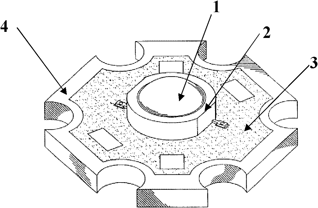
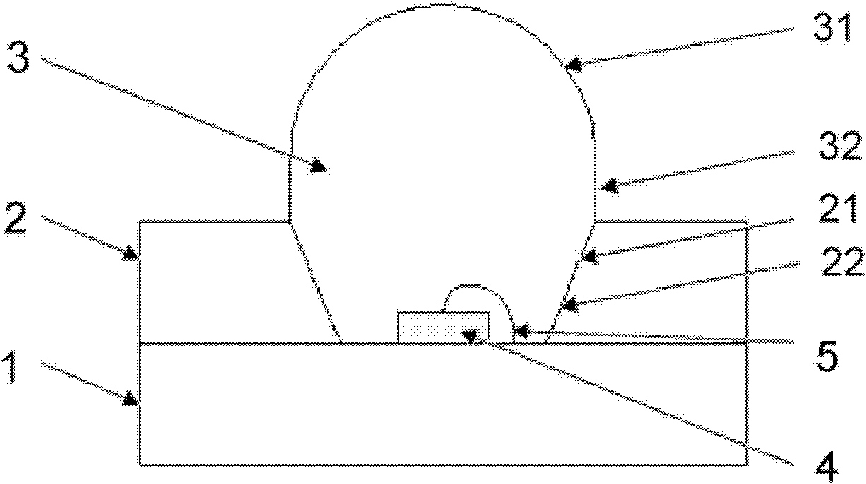
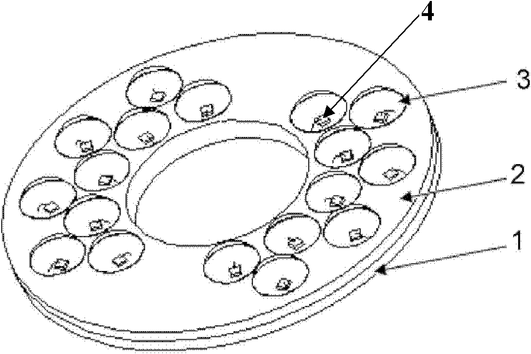
[0028] The first embodiment of the present invention relates to an LED light board. figure 2 It is a schematic diagram of the structure of a single LED chip of the LED light board, image 3 , Figure 4 , Figure 5 They are the perspective view, section view and top view of the LED light panel respectively. The LED lamp board includes: a base ...


PUM


Abstract

The invention relates to the field of LED (light-emitting diode) lightening, and discloses an LED (light-emitting diode) lamp panel. The LED lamp panel in the invention comprises a baseplate, a light-gathering plate, an LED chip and a lens, wherein the baseplate is made of a heat conducting material, the light-gathering plate is provided with a through hole and positioned on the baseplate, and the LED chip is arranged in the through hole and appressed on the baseplate; and the whole through hole is filled with a transparent colloid so as to form the lens after the transparent colloid is solidified. The LED lamp panel provided by the invention can be used for solving the problems that the heat dissipation of a high-power LED lamp is bad, the ray emergent medium is oversize and further serious lumens depreciation is caused; and the LED lamp panel provided by the invention has the advantages of good heat dissipation effect, high ray use ratio, long service life and the like.

Description

technical field [0001] The invention relates to the field of LED lighting, in particular to an LED lamp board. Background technique [0002] Substrate: It consists of a circuit layer (copper foil layer), a thermally conductive insulating layer and a metal base layer. The circuit layer is required to have a large current-carrying capacity, so thicker copper foil should be used, the thickness is generally 35 μm to 280 μm; the heat-conducting insulating layer is the core technology of the substrate, and it is generally composed of a special polymer filled with special ceramics. Small thermal resistance, excellent viscoelastic performance, thermal aging resistance, and ability to withstand mechanical and thermal stress; the metal base layer is the supporting member of the substrate, which requires high thermal conductivity, usually an aluminum plate, and a copper plate can also be used (the copper plate can provide Better thermal conductivity), suitable for conventional machini...

Claims


Application Information

Patent Timeline
Patent Type & Authority Applications(China)
IPC IPC(8): F21S2/00F21V23/00F21V13/04F21V19/00F21V29/00F21Y101/02F21V29/85
Inventor 刘明新金升阳
Owner HANGZHOU HIKVISION DIGITAL TECH
Why Eureka
Try Eureka