Optical displacement sensor

A technology of displacement sensor and sensor, which is applied in the direction of adopting optical devices, instruments, measuring devices, etc., can solve problems such as complex production, achieve the effects of eliminating influencing factors, simple structure and principle, and improving detection sensitivity

Inactive Publication Date: 2013-03-06
NANJING UNIV OF POSTS & TELECOMM
View PDF0 Cites 0 Cited by
  • Summary
  • Abstract
  • Description
  • Claims
  • Application Information

AI Technical Summary

Problems solved by technology

Optical methods are widely used in non-contact displacement sensors, such as optical fiber displacement sensing technology [3] , optical interference technology [4] , Grating metrology technology [5] etc., but they generally require high operating precision, and the production is relatively complicated

Method used


Image

  • Optical displacement sensor
  • Optical displacement sensor
  • Optical displacement sensor

Examples


Embodiment 1

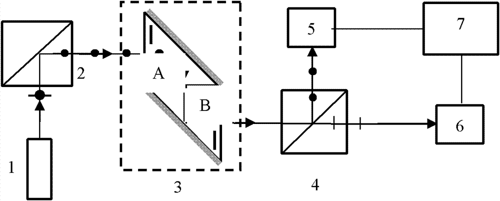
[0040] The device used in an optical displacement sensor of the present invention is as figure 1 shown. figure 1Among them, 1 is the laser. 2 is the first polarizing beam splitting prism. 3 is a displacement sensing element, which is composed of two isosceles right-angled triangle quartz crystal prisms A and B with the same structure and performance on the upper and lower sides. A and B glue their horizontal bottom surfaces together through optical glue to form a An overall sensing element; one of A and B is required to be a positive crystal, and the other is a negative crystal; the slopes are respectively coated with polarization-maintaining reflective films, so that the polarization state of the light does not change when the light is reflected on the slopes; the optical axes of crystals A and B The direction is perpendicular to its two bottom surfaces, as shown by the marking line "|" in the quartz crystal in the figure. The laser light emitted by the laser 1 is reflecte...

specific Embodiment 2

[0061] The device used in an optical displacement sensor of the present invention is as figure 1 shown. figure 1 1 is the laser. 2 is the first polarizing beam splitting prism. 3 is a displacement sensing element, which is composed of two isosceles right-angled triangle quartz crystal prisms A and B with the same structure and performance on the upper and lower sides. The two bottom surfaces of A and B are glued together by optical glue to form a The overall sensing element; one of A and B is required to be a positive crystal, and the other is a negative crystal; the slopes are respectively coated with polarization-maintaining reflective film, so that the polarization state of the light does not change when the light is reflected on the slope; the direction of the optical axis of crystals A and B It is perpendicular to its two bottom surfaces, as shown by the marking line "|" in the quartz crystal in the figure. The laser light emitted by the laser 1 is reflected by the fir...


PUM


Abstract

The invention provides an optical displacement sensor based on the principle of optical rotation effect of quartz crystals. Positive and negative isosceles right-triangular quartz crystal prisms are adopted in the optical displacement sensor and the change of displacement is converted into the change of an optical rotation angle, so as to acquire displacement information by detecting the receivedlight intensity. The optical displacement sensor comprises a laser device (1), a first polarization beam splitter prism (2), a displacement sensing element (3), a second polarization beam splitter prism (4), a first photoelectric detector (5), a second photoelectric detector (6) and a division arithmetic unit (7) which are arranged in sequence, wherein the displacement sensing element (3) is composed of a first quartz crystal prism (A) and a second quartz crystal prism (B) which are arranged up and down, have identical shapes and properties, have positive and negative specific rotary powers and are in the shape of an isosceles right-triangle; the two opposite bottoms of the first quartz crystal prism (A) and the second quartz crystal prism (B) are integrally glued by use of an optical cement; and the optical axis directions of the first quartz crystal prism (A) and the second quartz crystal prism (B) are vertical to the two opposite bottoms.

Description

technical field [0001] The invention relates to an optical displacement sensor, belonging to the technical fields of photoelectric detection, photoelectric sensing and optical information processing. Background technique [0002] Displacement is one of the common and important physical quantities in engineering testing. Physical quantities such as stress, temperature, and velocity can be indirectly measured through displacement testing. [1] . Displacement detection technology is a detection method that converts displacement into other measurable physical quantities that have a definite relationship with it. With the development of industrial technology, displacement detection has become very important and widely used, such as scientific and technological measurement, automatic devices, machine tool control, etc. Displacement sensors are mainly divided into two types: contact type and non-contact type. Contact type displacement sensors are generally based on electronic tech...

Claims


Application Information

Patent Timeline
Patent Type & Authority Patents(China)
IPC IPC(8): G01B11/02
Inventor 梁忠诚沈骁
Owner NANJING UNIV OF POSTS & TELECOMM
Why Eureka
Try Eureka