Electro-optic Phase Modulator with Automatic Adjustment of Resonant Frequency

An electro-optic phase modulation and phase modulator technology, applied in the field of photoelectric detection, can solve the problems of affecting the modulation effect, reducing the modulation efficiency, time-consuming and laborious, etc., and achieve the effects of improving modulation efficiency, saving time, and improving work efficiency

Active Publication Date: 2011-12-14
SHANGHAI MICRO ELECTRONICS EQUIP (GRP) CO LTD +1
View PDF5 Cites 8 Cited by
  • Summary
  • Abstract
  • Description
  • Claims
  • Application Information

AI Technical Summary

Problems solved by technology

[0013] The present invention aims at the problem that the modulation efficiency decreases and even affects the modulation effect caused by the impedance mismatch between the modulation power supply of the electro-optic phaser and the electro-optic phase modulator during the application process of the existing electro-optical phase modulation technology. The existing adjustment device and method To solve the problem of time-consuming and labor-intensive problems, a design scheme and device for electro-optical phase modulator with the function of automatically adjusting the resonance frequency are proposed. And adjust the resonant frequency of the electro-optical phase modulator in real time according to the detection results to match the frequency of the output signal of the electro-optic phase modulation power supply, so as to achieve the purpose of improving the modulation efficiency. Moreover, through real-time online adjustment, it can avoid the need for system stop in the existing adjustment method Disadvantages that can only be adjusted after work and disassembly of the electro-optic phase modulator, improve system adjustment efficiency and use efficiency

Method used


Image

  • Electro-optic Phase Modulator with Automatic Adjustment of Resonant Frequency
  • Electro-optic Phase Modulator with Automatic Adjustment of Resonant Frequency
  • Electro-optic Phase Modulator with Automatic Adjustment of Resonant Frequency

Examples


Embodiment approach 1

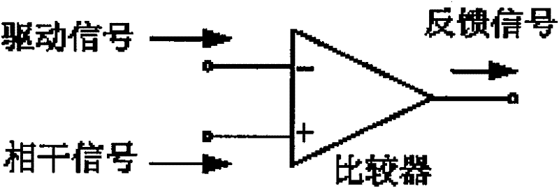
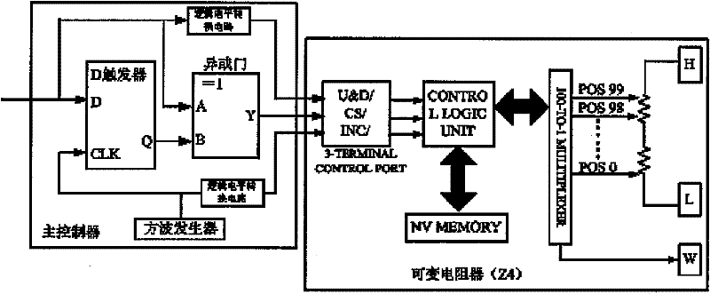
[0072] Such as Figure 9As shown, the main controller unit 27 of the electro-optic phase modulator tracks the matching situation between the resonant frequency of the phase modulator and the frequency of the modulation signal output by the modulation power supply according to the feedback signal of the feedback signal generating unit 24, and adjusts the resonant frequency point of the phase modulator in real time . The feedback signal from the feedback signal generation unit 24 is delivered to the D flip-flop of the main controller unit 27 of the electro-optic phase modulator, and is triggered by the clock terminal (CLK end) of the D flip-flop to be delivered to the output terminal, and the output terminal of the D flip-flop is connected to the output terminal. The feedback signal from the feedback signal generation unit 24 is subjected to an exclusive OR operation through an exclusive OR gate circuit to realize the judgment of the matching state between the frequency of the m...

Embodiment approach 2

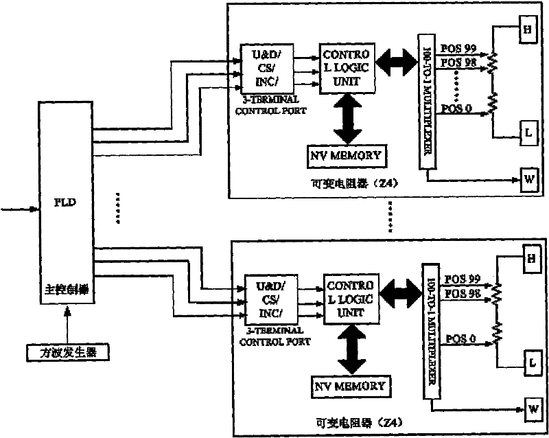
[0074] Due to the adjustable resistor Z 4 It is a digital control method and is not continuously adjustable. Therefore, multiple adjustable resistors can be selected in series according to actual needs to adopt multi-level control. Multiple different adjustable resistors are composed of multiple channels in series for adjustment, so as to achieve high-precision and wide-range adjustment. To achieve the purpose of improving the adjustment accuracy. but Figure 9 Using the multi-level control method in the method shown will increase the number of components, thereby increasing the number of components and the layout area of ​​the control circuit, and increasing the volume of the phase modulator.

[0075] Such as Figure 10 As shown, the main controller unit 27 of the electro-optical phase modulator is mainly composed of programmable logic devices (PLDs), and programmable logic devices (such as FPGA chips, single-chip microcomputer chips, etc.) can provide multiple IOs and real...


PUM


Abstract

The invention discloses an electro-optical phase modulator, which comprises an electro-optical phase modulating crystal, a power extraction unit, a modulating power detection unit, a coherent power detection unit, a feedback signal generating unit, an electro-optical phase modulating crystal parallel resonant circuit, a main controller unit and an electro-optical phase modulator shielding shell, wherein the power extraction unit is used for extracting the power and a driving signal of an input modulating signal and the power of a coherent signal of a phase modulator reflected signal; the modulating power detection unit is used for converting the power of the extracted modulating signal into a voltage value; the coherent power detection unit is used for converting the extracted power of the coherent signal into a voltage value; the feedback signal generating unit is used of providing a feedback signal according to signals output by the modulating power detection unit and the coherent power detection unit; the main controller unit is used for acquiring and judging the feedback signal provided by the feedback signal generating unit, controlling the inductance value of the parallel resonant circuit according to a judgment result and automatically changing the resonant frequency point of the phase modulator till the resonant frequency point is matched with a modulating signal frequency; the resonant frequency of the phase modulator is always matched with a modulating signal frequency value output by a modulating power supply; and the electro-optical phase modulator shielding shell is used for protecting each component inside the electro-optical phase modulator and isolating external electromagnetic interference signals.

Description

technical field [0001] The invention relates to the field of photoelectric detection technology, in particular to an electro-optic phase modulator resonance frequency detection device and detection method, which are applied to the electro-optic phase modulator resonance frequency detection and calibration in a photoelectric detection system. Background technique [0002] In the field of weak photoelectric detection, due to the inevitable existence of a certain number of multi-order reflection ghost beams in the process of beam transmission in the optical system, the ghost beams generated after multiple reflections have the same phase and frequency as the main beam at the same point. The phase and frequency are exactly the same, which causes interference between the ghost beam and the main beam, resulting in a deviation between the detected optical signal and the ideal optical signal, resulting in a corresponding measurement error in the actual measurement result. In order to...

Claims


Application Information

Patent Timeline
Patent Type & Authority Applications(China)
IPC IPC(8): G02F1/03G01R23/02
Inventor 唐文力陈振飞王海江
Owner SHANGHAI MICRO ELECTRONICS EQUIP (GRP) CO LTD
Why Eureka
Try Eureka