
Plasma treatment device

A plasma and processing device technology, applied in the field of plasma processing devices, can solve problems such as uneven wafers, and achieve the effects of eliminating standing wave effects, uniform etching rate, and uniform energy distribution

Active Publication Date: 2011-12-14
ADVANCED MICRO FAB EQUIP INC CHINA
View PDF4 Cites 5 Cited by
  • Summary
  • Abstract
  • Description
  • Claims
  • Application Information

AI Technical Summary

Problems solved by technology

[0007] The problem solved by the embodiments of the present invention is to provide a plasma processing device, which solves the problem of unevenness of the wafer after processing by the existing plasma processing device

Method used


Image

  • Plasma treatment device
  • Plasma treatment device
  • Plasma treatment device

Examples


Embodiment Construction

[0032] The uniformity of wafers processed by existing plasma processing devices cannot meet process requirements. After research by the inventor, it was found that the uniformity of the processed wafer was not good due to the uneven distribution of the plasma on the wafer surface during the process, and the reason for the uneven distribution of the plasma on the wafer surface was: the application of radio frequency signals The energy distribution of the first electrode or the second electrode close to the surface of the wafer to be processed (the energy in the vacuum processing chamber) is uneven.

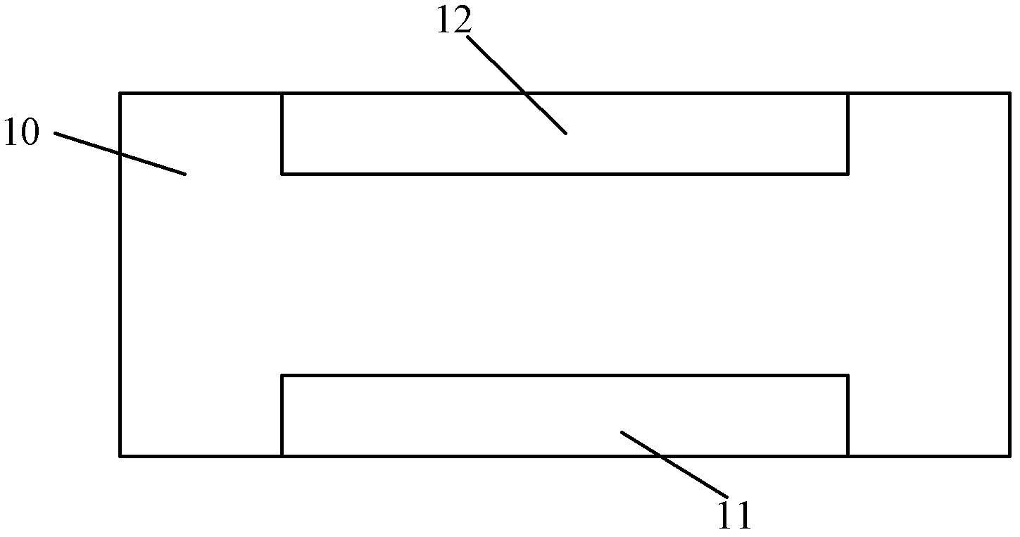
[0033] Please combine figure 1 , taking a plasma processing device applied to a plasma etching process as an example, a radio frequency signal is applied on the second surface of the first electrode 11, and the radio frequency signal is transmitted from the second surface to the first surface along the outside of the first electrode 11 , when the radio frequency signal is a high f...


PUM


Abstract

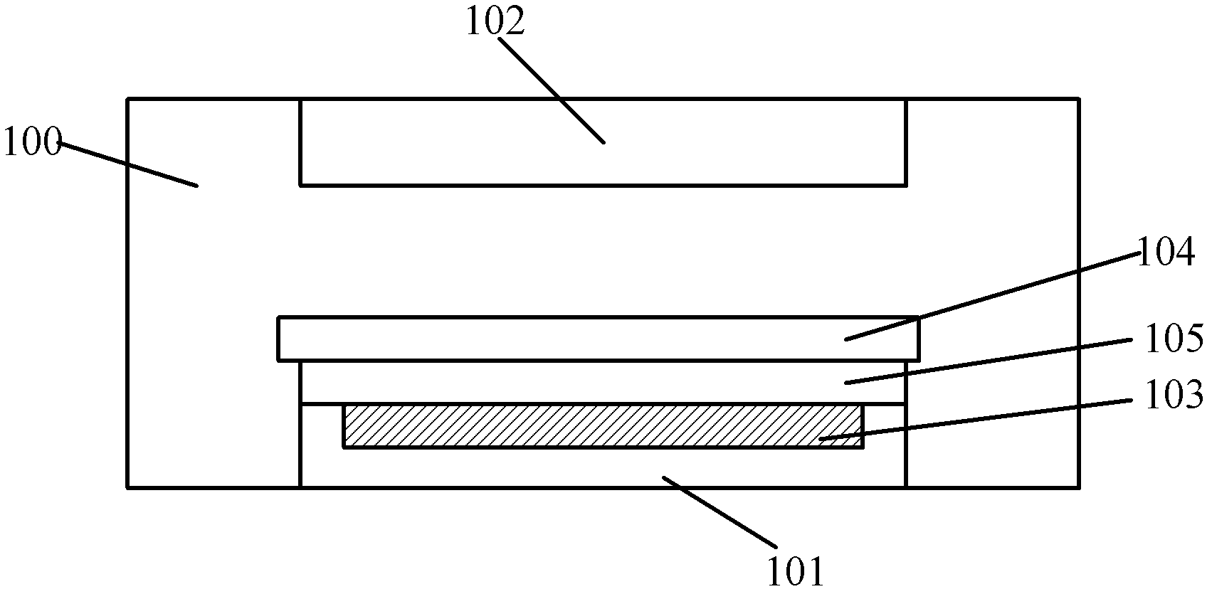
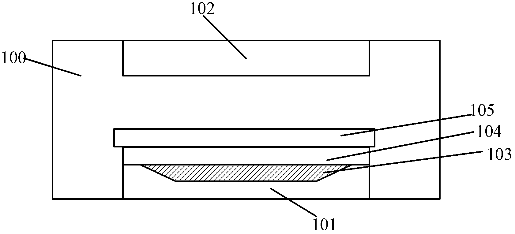
The embodiment of the invention provides a plasma treatment device. The plasma treatment device comprises a vacuum treatment cavity, a first electrode, and a non-dielectric material layer, wherein the first electrode is positioned in the vacuum treatment cavity; a platform for placing wafers to be treated is arranged above the first electrode; the first electrode is electrically connected with two radio frequency power supplies, and the frequency of a first radio frequency source is 1.5 times higher than that of a second radio frequency source; the non-dielectric material layer is positioned between the first electrode and the platform for placing the wafers to be treated; and the resistivity of the non-dielectric material layer is higher than that of the first electrode. The plasma treatment device provided by the embodiment of the invention improves the distribution uniformity of plasmas in the vacuum treatment cavity and improves the uniformity of the wafers which are treated by the plasma treatment device.

Description

technical field [0001] The invention relates to the technical field of semiconductors, in particular to a plasma processing device. Background technique [0002] At present, in the manufacturing process of semiconductor devices, etc., a capacitively coupled plasma processing device is usually used to generate gas plasma to react with the surface of the wafer, so as to realize the corresponding process on the wafer. The process may be a plasma etching process or a plasma enhanced chemical vapor deposition process. [0003] Please combine figure 1 The schematic diagram of the structure of the existing plasma processing device is shown. The plasma processing device is a capacitive coupling type. Specifically, the plasma processing device includes: a vacuum processing chamber 10 for introducing a reaction gas. The first electrode 11 and the second electrode 11 are arranged in parallel in the vacuum processing chamber 10. Two electrodes 12, between the first electrode 11 and t...

Claims


Application Information

Patent Timeline
Patent Type & Authority Applications(China)
IPC IPC(8): H01J37/32H01J37/30
Inventor 倪图强欧阳亮吴狄陶铮松尾裕史
Owner ADVANCED MICRO FAB EQUIP INC CHINA
Learn More