Coaxial-ridge waveguide-microstrip conversion structure power divider

A technology of coaxial waveguide and conversion structure, applied in waveguide-type devices, electrical components, connecting devices, etc., can solve the problems of narrow bandwidth, large loss, and small number of power division/combination ports, and achieve low loss and large amount of power. The number of branches and the power division signal have good amplitude and phase consistency

Inactive Publication Date: 2011-12-14
UNIV OF ELECTRONIC SCI & TECH OF CHINA
View PDF3 Cites 33 Cited by
  • Summary
  • Abstract
  • Description
  • Claims
  • Application Information

AI Technical Summary

Problems solved by technology

[0004] The purpose of the present invention is to provide an ultra-wideband multi-channel power splitter, which overcomes the defects of narrow bandwidth, large loss, and small number of power splitting/combining ports in the existing power combining technology, so that the power split

Method used


Image

  • Coaxial-ridge waveguide-microstrip conversion structure power divider
  • Coaxial-ridge waveguide-microstrip conversion structure power divider
  • Coaxial-ridge waveguide-microstrip conversion structure power divider

Examples


Embodiment 1

[0028] This example is a coaxial-ridge waveguide-microstrip conversion structure ultra-wideband four-way power splitter.

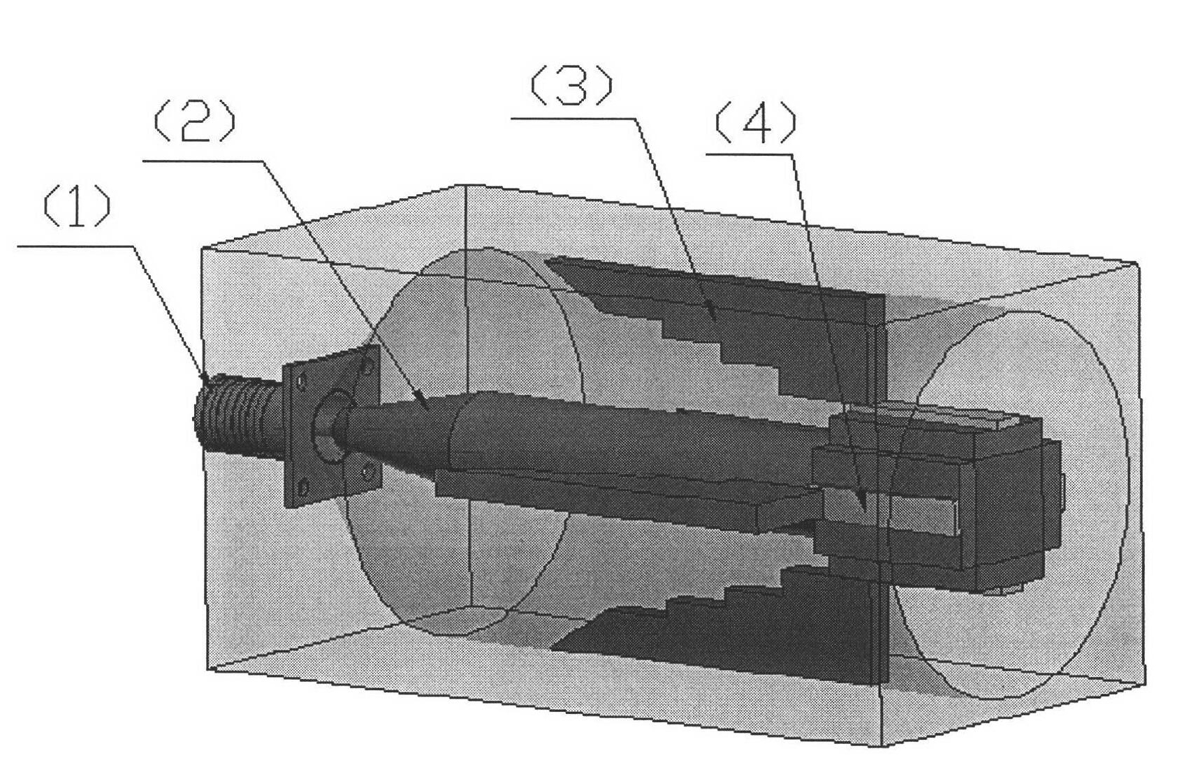
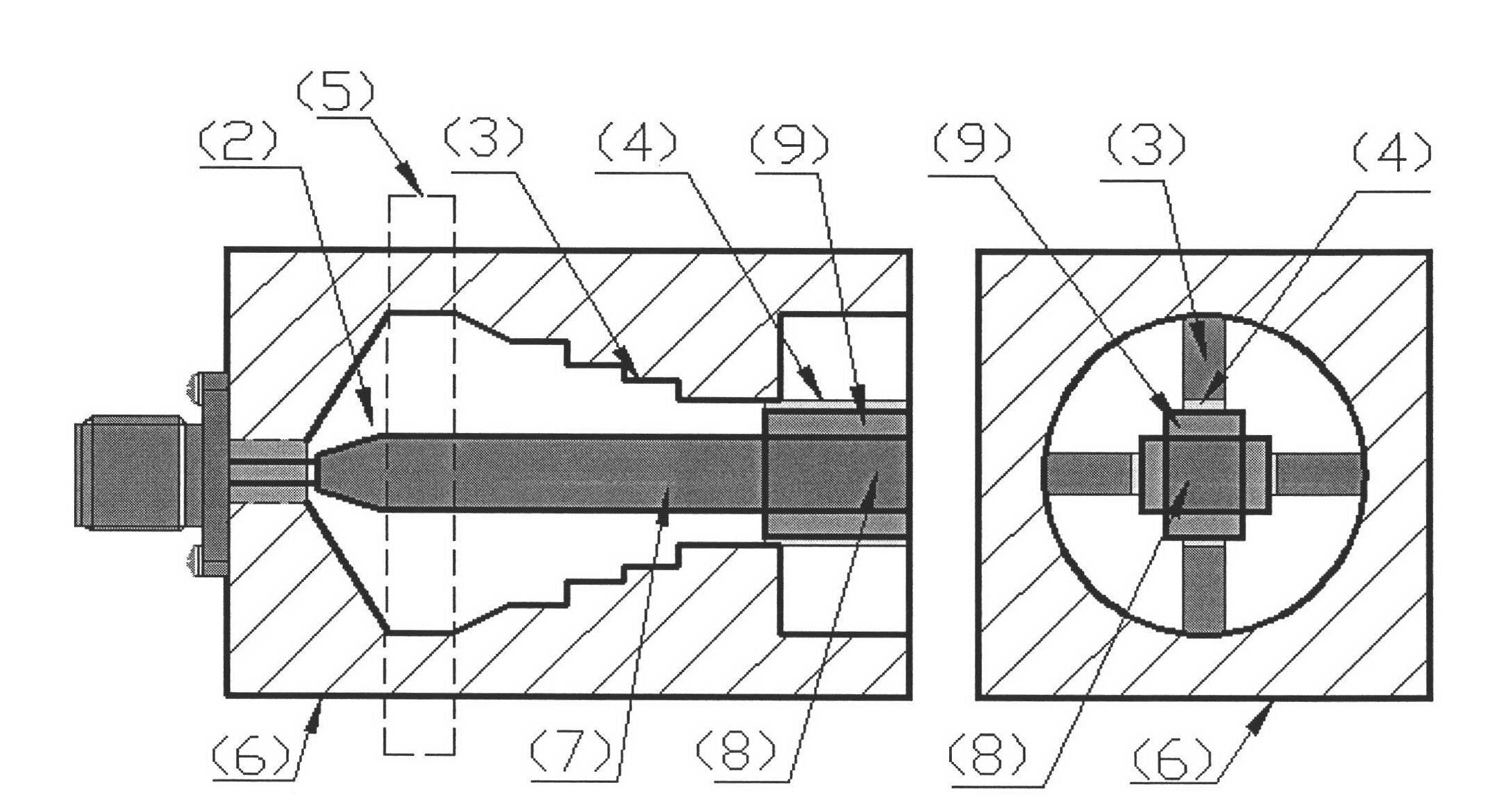
[0029] like figure 1 and figure 2 shown. The new four-way power splitter based on the extended coaxial waveguide proposed by the present invention includes five parts, namely: the SMA coaxial connector at the signal input port of the power splitter; the conical coaxial joint between the SMA coaxial connector and the extended coaxial waveguide Gradient transition; extended coaxial waveguide; four-way coaxial-ridge waveguide-microstrip conversion structure; microstrip line output port.

[0030] The SMA coaxial connector at the input port of the power divider adopts a commercial standard SMA connector, and its parameters are: the outer radius of the inner conductor is r=0.65mm, and the inner radius of the outer conductor is R=2.1mm. The tapered coaxial gradual transition is a linear transition from the inner and outer conductors of the SMA coaxial connect...

Embodiment 2

[0034] This example is a coaxial-ridge waveguide-microstrip conversion structure ultra-wideband sixteen-way power splitter.

[0035] like Figure 4 shown. The structure of the sixteen-way ultra-broadband power divider proposed by the present invention is similar to that of the four-way power divider, except that the extended coaxial waveguide contains sixteen-way coaxial-ridge waveguide-microstrip conversion structures and sixteen Line output port, so as to realize sixteen signal power distribution. The parameters of the length, width and height of the sixteen ridge waveguides are exactly the same, so as to ensure that the power division signals at the output ports of the sixteen microstrip lines have the same phase and amplitude.

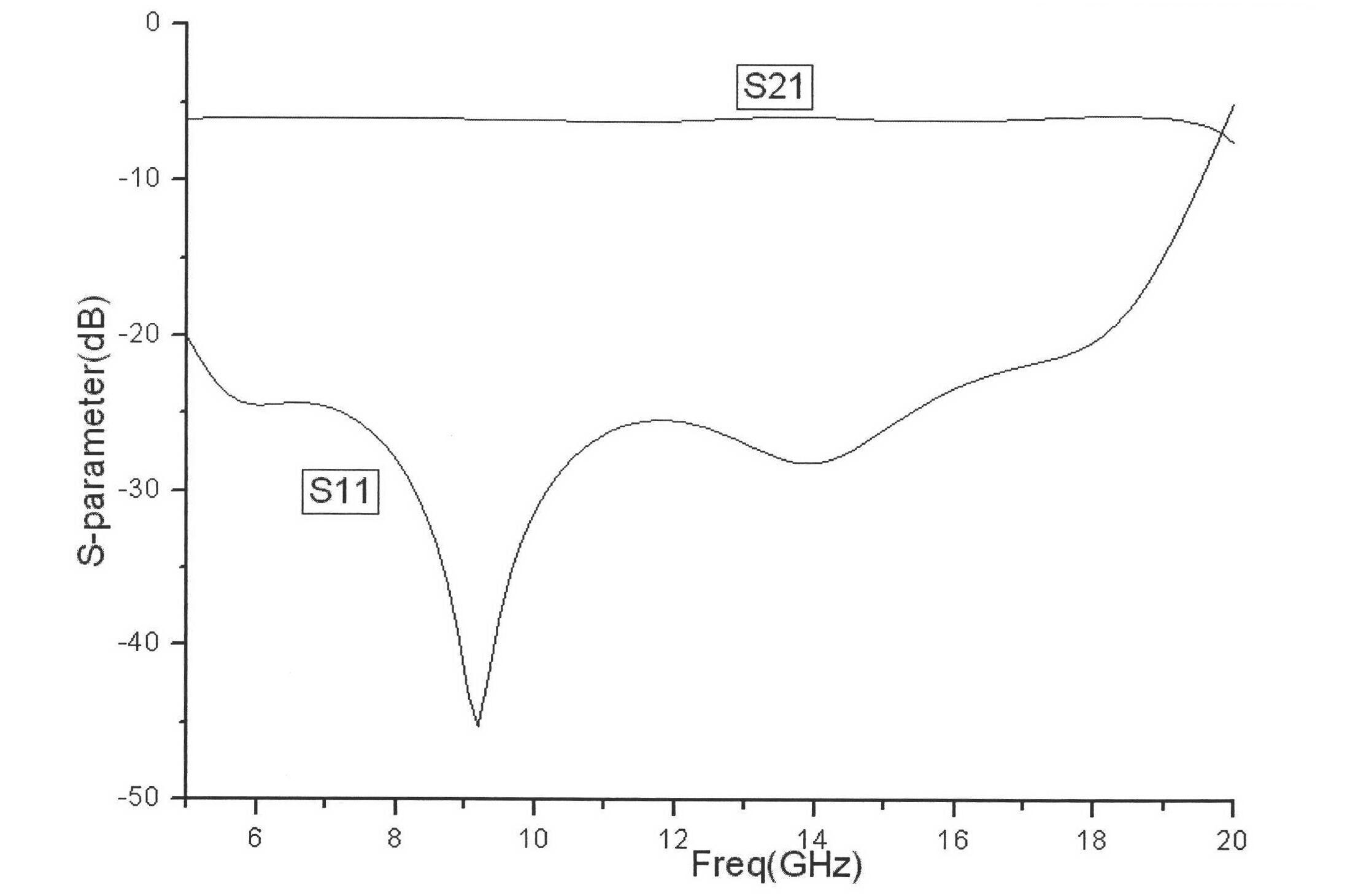
[0036] The S parameters of the sixteen-way ultra-wideband extended coaxial power divider are as follows: Figure 5shown. In the invention, the reflection loss is less than -20dB in the frequency range from 6.7GHz to 19.3GHz, the insertion loss ...


PUM

PropertyMeasurementUnit
Return lossaaaaaaaaaa
Insertion lossaaaaaaaaaa

Abstract

The invention relates to a coaxial-ridge waveguide-microstrip conversion structure ultra-broadband multi-channel power splitter. The input coaxial joint and the extended coaxial waveguide adopt a tapered coaxial gradual transition, and the tapered coaxial gradual transition And the ridge waveguide-microstrip conversion structure can realize ultra-wideband impedance matching; N ridge waveguide-microstrip conversion structures are uniformly distributed along the circumference in the extended coaxial waveguide to realize N-way parallel power division, and the entire power division circuit has axisymmetric To ensure that the signal amplitudes and phases of the N-channel power division signals are equal, the N-channel signal power division can be realized in one step, which can minimize the signal transmission loss. The present invention has ultra-wideband, low transmission loss, can realize any multi-channel power division output, each power division output signal has good amplitude and phase consistency, flat group delay characteristics in the band, and is easy to integrate with other peripheral planar circuits, etc. advantage. The invention is mainly used in microwave and millimeter wave power synthesis amplification systems, array antennas, etc., and has broad application prospects in microwave and millimeter wave systems such as communication and radar.

Description

technical field [0001] The invention relates to a spatial power divider based on an extended coaxial waveguide, in particular to a novel ultra-wideband multi-channel power splitter with a coaxial-ridge waveguide-microstrip conversion structure. Background technique [0002] With the rapid development of military and civilian communication systems, the demand for high-efficiency, broadband high-power amplifiers is increasing day by day. The output power of a single solid-state device is far from meeting the requirements of power applications due to the influence of its own semiconductor physical characteristics and the limitations of processing technology, heat dissipation, and impedance matching. In order to solve this problem, people have studied the method of using multiple solid-state devices for power distribution, amplification, and synthesis to obtain high power output, that is, solid-state power synthesis technology. Therefore, the broadband multi-channel power divid...

Claims


Application Information

Patent Timeline
IPC IPC(8): H01P5/12
Inventor 宋开军马亮樊勇陈宁波
Owner UNIV OF ELECTRONIC SCI & TECH OF CHINA
Why Eureka
Try Eureka