Apparatus and method for measuring dispersion of optical fiber optics

A technology of fiber optics and measuring devices, which is applied in the field of optical measurement, can solve the problems of low dispersion measurement accuracy and complicated measurement process, and achieve the effects of avoiding interference, easy operation, and accurate measurement

Inactive Publication Date: 2011-12-14
DALIAN UNIV OF TECH
View PDF3 Cites 32 Cited by
  • Summary
  • Abstract
  • Description
  • Claims
  • Application Information

AI Technical Summary

Problems solved by technology

[0011] In order to solve the technical problems of low dispersion measurement accuracy

Method used


Image

  • Apparatus and method for measuring dispersion of optical fiber optics
  • Apparatus and method for measuring dispersion of optical fiber optics
  • Apparatus and method for measuring dispersion of optical fiber optics

Examples


Embodiment

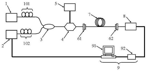
[0050] figure 1 It is a structural schematic diagram of the fiber optic device dispersion measuring device of the present invention. The light waves output by the fixed-wavelength laser 1 and the tunable laser 2 pass through the first polarization controller 101 and the second polarization controller 102 respectively and enter the fiber coupler 3 to combine into one path, and then enter the electro-optic modulator 4, and the light waves output by the microwave signal source 5 The microwave signal is modulated on the two light waves by the electro-optic modulator 4, and the microwave-modulated optical carrier enters the fiber optic device 7 to be tested through the first optical connector 61, and the fiber optic device 7 to be tested is connected to the photoelectric detector by the second optical connector 62. The photodetector 8 converts the input optical signal into a microwave electrical signal, and the microwave electrical signal is collected by the data acquisition card 9...


PUM


Abstract

The invention discloses a fiber optical device dispersion measurement device and method, belonging to the field of optical measurement. The device includes: a fixed wavelength laser, a tunable laser, a fiber coupler, an electro-optic modulator, a microwave signal source, a first optical connector, a second optical connector, an optical fiber optic device to be tested, a photodetector, and data acquisition and processing system. The invention solves the technical problems of low dispersion measurement precision and complicated measurement process in the prior art, and has the advantages of strong anti-interference ability, high measurement precision and convenient operation.

Description

technical field [0001] The invention belongs to the field of optical measurement, in particular to a device and method for measuring dispersion of optical fiber optics. Background technique [0002] Dispersion is an important parameter of the characteristics of optical fiber optics, and also one of the important factors affecting the performance of optical fiber communication systems and microwave optical fiber transmission systems. In high-speed optical fiber communication systems, fiber dispersion will lead to pulse broadening, which will increase the bit error rate; in high-frequency microwave optical fiber transmission systems, the accumulation of fiber dispersion will lead to attenuation of microwave power. Certain measures are usually taken, such as dispersion compensating fiber or dispersion compensating functional devices (fiber grating, waveguide microring resonator, etc.) to compensate the fiber dispersion, thereby improving the performance of the transmission sys...

Claims


Application Information

Patent Timeline
IPC IPC(8): H04B10/08H04B10/12G01M11/02H04B10/073
Inventor 韩秀友李善锋赵明山谷一英张敏王勐
Owner DALIAN UNIV OF TECH
Why Eureka
Try Eureka