A flue gas waste heat power generation system for aluminum electrolytic cell with flue gas separation device

A power generation system, flue gas waste heat technology, applied in steam engine installations, machines/engines, mechanical equipment, etc., can solve the problem that the waste heat of electrolytic aluminum equipment cannot be effectively recycled.

Inactive Publication Date: 2011-12-21
BEIJING CENTURY BENEFITS
View PDF7 Cites 13 Cited by
  • Summary
  • Abstract
  • Description
  • Claims
  • Application Information

AI Technical Summary

Problems solved by technology

[0005] In order to solve the problem that the waste heat of electrolytic aluminum equipment in the prior art cannot be effectively recycled, the present invention provides an aluminum electrolytic cell flue gas waste heat power generation system, which uses the waste heat of the anode high-temperature flue gas in the aluminum electrolytic cell to generate electricity. A flue gas separation device is installed in the electrolytic cell to separate the high-temperature flue gas produced by the high-temperature anode side reaction from the mixed low-temperature cold air, extract the medium-high temperature flue gas with a temperature of 400 ° C ~ 500 ° C, and pass it into the waste heat boiler to generate steam. Reuse of turbo-generator system for power generation

Method used


Image

  • A flue gas waste heat power generation system for aluminum electrolytic cell with flue gas separation device
  • A flue gas waste heat power generation system for aluminum electrolytic cell with flue gas separation device
  • A flue gas waste heat power generation system for aluminum electrolytic cell with flue gas separation device

Examples


Embodiment Construction

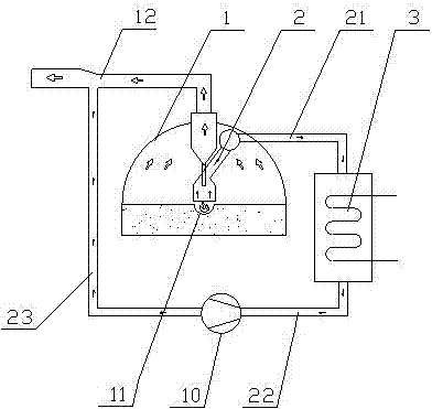
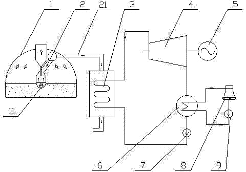
[0019] An embodiment of the present invention provides a flue gas waste heat power generation system of an aluminum electrolytic cell with a flue gas separation device, which is used to recover the waste heat of the flue gas of an aluminum electrolytic cell to generate electricity. This system is composed of flue gas system, waste heat boiler system, steam turbine generator set, condensing system and supporting electrical and control systems.

[0020] Such as figure 1 , 2 As shown, the flue gas system includes a flue gas separation device 2 arranged in the aluminum electrolytic cell 1, an induced draft fan 10, a first flue gas pipeline 21 for connecting the flue gas separation device and the waste heat boiler system, and a first flue gas pipeline 21 for connecting the waste heat boiler and the waste heat boiler system. The second flue gas duct 22 of the induced draft fan 10 and the third flue gas duct 23 for connecting the induced draft fan 10 and the original flue gas duct 1...


PUM


Abstract

An aluminum electrolytic cell flue gas waste heat power generation system with a flue gas separation device includes a flue gas system, a waste heat boiler system, a steam turbine generator set, an electrical and a control system; the flue gas system is used to collect the high temperature generated by the anode of the aluminum electrolytic cell Flue gas, and send the high-temperature flue gas into the waste heat boiler system. The high-temperature flue gas performs heat exchange in the waste heat boiler system to generate steam, and the steam enters the turbogenerator unit for power generation; the electrical and control systems are used for the flue gas system. , waste heat boiler system, and steam turbine generator set provide power and coordinated control. The invention separates the high-temperature electrolysis flue gas through the flue gas separation device of the aluminum electrolytic cell, and inputs the flue gas into the waste heat boiler to generate steam, and then drives the steam turbine to rotate to drive the generator to generate electricity. The high-temperature flue gas can improve the steam parameters of the waste heat boiler and the waste heat recovery efficiency, and the improvement of the steam parameters can increase the operating efficiency of the steam turbine. The combined effect of the two improves the recovery rate of waste heat from the flue gas and the power generation of the waste heat power station.

Description

technical field [0001] The invention relates to an aluminum electrolytic cell flue gas waste heat power generation system with a flue gas separation device. Background technique [0002] At present, electrolytic aluminum, that is, cryolite-alumina molten salt electrolysis is usually used to produce metal aluminum. Among them, molten cryolite is used as a solvent, and alumina is used as a solute, and it is electrolyzed using an anode and a cathode of carbonaceous materials in the temperature range of 950 ° C to 970 ° C. After the direct current is applied, the aluminum liquid concentrates on the cathode, while the oxygen moves to the anode; during the electrolysis process, the anode also produces side reactions, and the main product of the anode side reactions is high-temperature flue gas, the main component of which is high-temperature flue gas Carbon dioxide and carbon monoxide gas, due to the high content of carbon monoxide, the high-temperature flue gas is also called el...

Claims


Application Information

Patent Timeline
Patent Type & Authority Applications(China)
IPC IPC(8): F01K27/02F01K11/02F01K25/10F01D15/10C25C3/06
Inventor 程珩陈恩鉴
Owner BEIJING CENTURY BENEFITS
Why Eureka
Try Eureka