Lift-drag type vertical axis wind driven generator based on overrunning combined mechanism

A technology of wind power generator and vertical axis, which is applied in the direction of wind power generator components, wind power engine, wind power motor combination, etc., which can solve the problems of low wind power generation efficiency, low reliability and poor stability, so as to improve the start-up performance and realize The effect of energy harvesting

Inactive Publication Date: 2013-09-04
HARBIN INST OF TECH
View PDF5 Cites 0 Cited by
  • Summary
  • Abstract
  • Description
  • Claims
  • Application Information

AI Technical Summary

Problems solved by technology

[0005] The purpose of the present invention is to provide a lift-drag type vertical-axis wind-driven generator based on a transcendent compound mechanism, so as to solve the problem of low wind power generation efficiency, poor stability and low reliability in existing intelligent composite vertical-axis wind-driven generators The problem

Method used


Image

  • Lift-drag type vertical axis wind driven generator based on overrunning combined mechanism
  • Lift-drag type vertical axis wind driven generator based on overrunning combined mechanism
  • Lift-drag type vertical axis wind driven generator based on overrunning combined mechanism

Examples


specific Embodiment approach 1

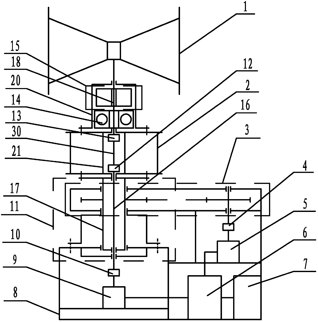
[0022] Specific implementation mode one: combine figure 1 and Figure 5 to Figure 10To illustrate, the lift-drag vertical axis wind power generator based on the transcending composite mechanism in this embodiment includes a lift wind wheel 1, a drag wind wheel 2, an overrunning compound mechanism 15, and a shaft center shaft transmission. Device 11, resistance wind wheel speed increasing device 3, lift wind turbine generator 9, resistance wind turbine generator 5, rectification controller 6, energy storage device 7, first coupling 13, second coupling 12, the first Three couplings 10, the fourth coupling 4, the first rolling bearing 14, the first resistance wind rotor shaft 20, the second resistance wind rotor shaft 21, the first lift wind rotor shaft 18, the second lift wind rotor shaft 30 and the fixed support 8 The first resistance wind wheel shaft 20 and the second resistance wind wheel shaft 21 are all provided with a hollow cavity, the resistance wind wheel 2 is installe...

specific Embodiment approach 2

[0029] Specific implementation mode two: combination figure 1 and Figure 5 ~ Figure 7 Illustrate that the overriding composite mechanism 15 in this embodiment includes a combination mechanism, a separation mechanism, an outer sleeve 32 and an inner sleeve 33; connection (connected by flat key 22 in this embodiment), the outer sleeve 32 is set on the inner sleeve 33, the outer sleeve 32 is arranged in the hollow cavity of the first resistance wind wheel shaft 20, and the outer sleeve 32 is connected with the first resistance wind wheel shaft 20 (in this embodiment In the method, screw 23 is used for connection); the separation mechanism includes two balls 34 and two first springs 35, and two gaps 36 are arranged on the outer wall of the inner sleeve 33, and the two gaps 36 are symmetrical with respect to the center line of the inner sleeve 33 Setting, each notch 36 is provided with a ball 34 and a first spring 35, one end of each first spring 35 is connected with the correspo...

specific Embodiment approach 3

[0033] Specific implementation mode three: combination Figure 7 To illustrate, the number of slider grooves 39 in this embodiment is 4-8. The exact amount is determined by the friction torque. Others are the same as in the second embodiment.


PUM


Abstract

The invention relates to a lift-drag type vertical axis wind driven generator based on an overrunning combined mechanism, in particular to a lift-drag type vertical axis wind driven generator aiming at the problems of low generating efficiency, poor stability and low reliability of a lift-drag combined type vertical axis wind driven generator. A drag force wind rotor is arranged on a second drag force wind rotor shaft; a first lift force wind rotor shaft and a second lift force wind rotor shaft are arranged in a first drag force wind rotor shaft and the second drag force wind rotor shaft; thesecond lift force wind rotor shaft is connected with the first lift force wind rotor shaft through a first coupling; the first lift force wind rotor shaft and the first drag force wind rotor shaft are provided with a lift force wind rotor and the drag force wind rotor; the overrunning combined mechanism is fixed between the first lift force wind rotor shaft and the first drag force wind rotor shaft; the second lift force wind rotor shaft is connected with a lift force wind rotor generator through a second coupling, a third coupling and a third lift force wind rotor shaft; a drag force wind rotor speed increaser is arranged on a third drag force wind rotor shaft; the drag force wind rotor speed increaser is connected with a drag force wind rotor generator through a forth coupling; and the lift force wind rotor generator and the drag force wind rotor generator are connected with an energy storing device through a rectifier controller. The lift-drag type vertical axis wind driven generator based on the overrunning combined mechanism is particularly suitable for power supply of a region with large variation ranges of wind speed and wind direction.

Description

technical field [0001] The invention relates to a lift-drag type vertical axis wind power generator, which belongs to the technical field of wind power generation devices. Background technique [0002] There are two types of existing wind generators, one is a horizontal axis wind generator and the other is a vertical axis wind generator. [0003] The wind rotor of the horizontal axis wind turbine rotates around the horizontal axis. The generator needs to be installed at a high position, so installation and maintenance are very difficult. At the same time, the blades of the horizontal axis wind turbine need to be cantilever mounted, which is extremely easy to damage , short service life. In addition, horizontal-axis wind turbines cannot use tensioning devices, so they have poor wind resistance, and horizontal-axis wind turbines also need a windward control device, so there are problems of complex structure, many failures, and high cost. [0004] Vertical axis wind turbines ...

Claims


Application Information

Patent Timeline
Patent Type & Authority Patents(China)
IPC IPC(8): F03D9/02F03D11/02F16D41/064F16H1/20F16H7/08
CPCY02E10/722Y02E10/72
Inventor 曲建俊李松信王坤阳曲华杰李佳琪
Owner HARBIN INST OF TECH
Why Eureka
Try Eureka