
Xenon lamp

A xenon lamp and lamp holder technology, applied in the field of xenon lamps, can solve the problems of affecting the luminous effect and the unreasonable structure of the discharge tube, and achieve the effect of avoiding the phenomenon of refraction

Active Publication Date: 2012-10-10
常熟林芝电子技术有限公司
View PDF5 Cites 7 Cited by
  • Summary
  • Abstract
  • Description
  • Claims
  • Application Information

AI Technical Summary

Problems solved by technology

[0004] The xenon lamp in the prior art needs to be equipped with an AC stabilizer when it is put into practical use, that is, an AC ballast, which leads to troublesome use, inconvenient installation and uneconomical
[0005] CN101915394A (patent application filed by the applicant) adds a reflective film to the narrow neck formed between the core tube section and the discharge tube section, so that the lamp body The working temperature of the cathode is stable when the one-way reflection is realized during operation, and the brightness is ideally improved and the light loss is not reduced due to the addition of the reflective film, and it is suitable to use a DC ballast that is significantly cheaper than an AC ballast, but it is still Not Enough To Get Rid Of (Get Rid Of) Ballasts Outright
[0006] In addition, because the structure of the discharge tube of the xenon lamp in the prior art is unreasonable, there is refraction when discharging, that is, when emitting light, which affects the luminous effect

Method used


Image

  • Xenon lamp

Examples


Embodiment Construction

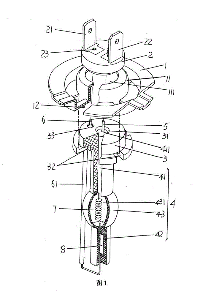
[0018] please see figure 1 , provides a generally disc-shaped lamp holder 1 preferably molded using a metal material, that is, stamped, for the current figure 1 The position state shown is taken as an example. In the center of the lamp holder 1 and on the upward side, there is a socket configuration boss 11 protruding from the plane (upper plane) of the lamp holder 1, and the boss 11 is arranged on the socket. The center of the tube is formed with a through lamp tube socket cavity 111 . And on the side of the lamp holder 1 facing the lamp holder 3 , that is, on the side facing downward of the lamp holder 1 and surrounding the opening of the lamp holder cavity 111 , a set of fixing buckle feet 12 extend at equal intervals. In this embodiment, the number of a group of fixed buckle feet 12 is 3, and each interval is 60° based on the circumferential direction of the lamp socket cavity 111, but the number of fixed buckle feet 12 is not affected by this embodiment. Quantity r...


PUM


Abstract

The invention relates to a xenon lamp, and belongs to the technical field of light source parts. The xenon lamp provided by the invention comprises a lamp holder, an insulation receptacle, a tube face, a strip lamp, a negative pole wire, a positive pole wire, an electron-tube heater, and a molybdenum slice, wherein the centre of the lamp holder is provided with a receptacle installation boss, andthe middle of the receptacle installation boss is provided with a tube face cavity; a first conducting pin and a second conducting pin are fixed on the insulation receptacle, and the middle of the tube face is provided with a core tube hole; the strip lamp is composed of a first core tube, a second core tube and a discharge tube, the first core tube is positioned in the core tube hole, and the discharge tube is formed between the first core tube and the core tube; one end of the positive pole wire is located on the tube face and connected with the first conducting pin, and the other end of the positive pole wire is connected with one end of the molybdenum slice; the molybdenum slice is packaged in the second core tube, and the other end of the molybdenum slice is connected with one end ofthe electron-tube heater; and the electron-tube heater is positioned at the interior of the discharge cavity of the discharge tube, the other end of the electron-tube heater is connected with one endof the negative pole wire, and the other end of the negative pole wire is connected with the second conducting pin. The xenon lamp provided by the invention has the advantages that the installation is convenient, the ideal economical efficiency is reflected, and the refraction phenomenon is avoided.

Description

technical field [0001] The invention belongs to the technical field of light source components, and in particular relates to a xenon lamp. Background technique [0002] The xenon lamp is filled with an inert chemical gas - xenon in an anti-ultraviolet crystal quartz glass tube. The white super-strong arc light produced by xenon can significantly increase the color temperature of the light, showing the sun's rays in daytime, and because the brightness generated by the xenon lamp is more than three times that of the traditional halogen lamp, and the service life is longer than the traditional one. Halogen lamps are more than ten times longer, so they are highly valued. [0003] Xenon lamps are widely used in vehicles because of their outstanding energy density and light intensity, which is very beneficial to expand the visual range in front of the vehicle and create a safer driving environment. However, xenon lamps are not limited to vehicle applications. For example, high-p...

Claims


Application Information

Patent Timeline
Patent Type & Authority Patents(China)
IPC IPC(8): F21V21/002F21V23/06H01J61/36
Inventor 陈东桥
Owner 常熟林芝电子技术有限公司
Learn More