An ultrasonic heat meter base tube

An ultrasonic and heat meter technology, applied in the field of ultrasonic heat meter base pipes, can solve the problems of the angle offset of the reflector, which cannot be used to collect signals, large pressure loss, blockage, etc., and achieves accurate measurement, stable signal, and small fluid resistance. Effect

Inactive Publication Date: 2011-12-21
TONGLING DERUIMAN ELECTRONICS TECH
View PDF5 Cites 4 Cited by
  • Summary
  • Abstract
  • Description
  • Claims
  • Application Information

AI Technical Summary

Problems solved by technology

The disadvantage of the above structure is: when the temperature is greater than 70 degrees Celsius, the large flow will generate pressure on the bracket, causing deformation, resulting in the angular deviation of the reflector and the collection signal cannot be used. Large, third, because there is no filter screen in the ultrasonic pipe section, fiber pollutants in the water are easy to hang on the plastic bracket and cause blockage

Method used


Image

  • An ultrasonic heat meter base tube
  • An ultrasonic heat meter base tube

Examples


Embodiment Construction

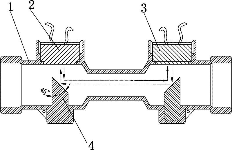
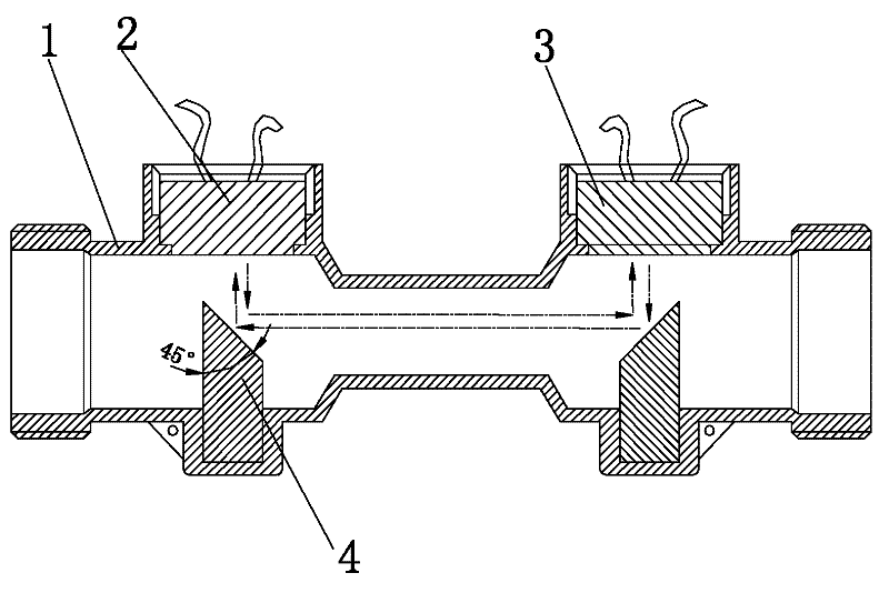
[0009] A kind of ultrasonic heat meter substrate tube of the present invention, as figure 1 As shown, it includes a tube body 1, a downstream transducer 2 attached to the tube body 1, and a countercurrent transducer 3 adapted to the downstream transducer 2. The tube body 1 is provided with a reflection block to make the downstream The ultrasonic waves emitted by the transducer can be received by the reverse flow transducer. The reflection block 4 is two metal cylinders, and the two metal cylinders are fixed on the pipe wall in the pipe body 1. In this embodiment, the inner wall of the pipe body 1 An outwardly protruding concave groove is provided, and the bottom of the reflection block 4 is embedded in the concave groove to be fixed. The upper end of the cylinder is provided with a reflective slope, the reflective slope is at an angle of 45 degrees to the cylinder, and the reflective surfaces of the two reflective blocks face each other, so that the ultrasonic wave emitted by ...


PUM


Abstract

The invention discloses a base tube of an ultrasonic heat meter, which comprises a tube body [1], a forward flow transducer [2] and a counterflow transducer [3]. The tube body [1] is provided with a reflective block. The reflective block [4] is two metal cylinders, the two metal cylinders are fixed on the pipe wall in the pipe body [1], the upper end of the cylinder is provided with a reflective slope, and the reflective surfaces of the two reflective blocks are opposite , so that the ultrasonic waves emitted by the downstream transducer [2] can be received by the upstream transducer [3] after being reflected by the two reflection blocks [4]. The invention has stable signal, accurate measurement, little resistance to the fluid in the pipeline and no blockage.

Description

technical field [0001] The invention relates to a base tube of an ultrasonic heat meter. Background technique [0002] The base tube of the ultrasonic heat meter is a device for accurately measuring the fluid in the tube. The commonly used ultrasonic heat meter base tube includes a tube body, a downstream transducer attached to the tube body, and a countercurrent transducer adapted to the downstream transducer. Reflector blocks are provided in the tube body to make the downstream transducer emit The ultrasonic wave can be received by the countercurrent transducer. There are two known structures at present. One is that the tube body and the copper shell of the ultrasonic meter are X-shaped, and the downstream transducer and the countercurrent transducer are respectively located at the two ends of the copper shell. At the end, the disadvantage of the above structure is that the forward flow transducer and the reverse flow transducer form an angle space with the pipe body. Whe...

Claims


Application Information

Patent Timeline
Patent Type & Authority Applications(China)
IPC IPC(8): G01K17/06G01F1/66
Inventor 崔后虎
Owner TONGLING DERUIMAN ELECTRONICS TECH
Why Eureka
Try Eureka