

Display device, liquid crystal panel, color filter and manufacturing method thereof
A color filter and manufacturing method technology, applied in the direction of optical filters, optics, optical components, etc., can solve the problems of product yield decline, uneven bonding, cost increase, etc., to improve product quality, reduce process difficulty, Effect of Product Yield Improvement
- Summary
- Abstract
- Description
- Claims
- Application Information
AI Technical Summary
Problems solved by technology
Method used
Image

Examples
Embodiment 1
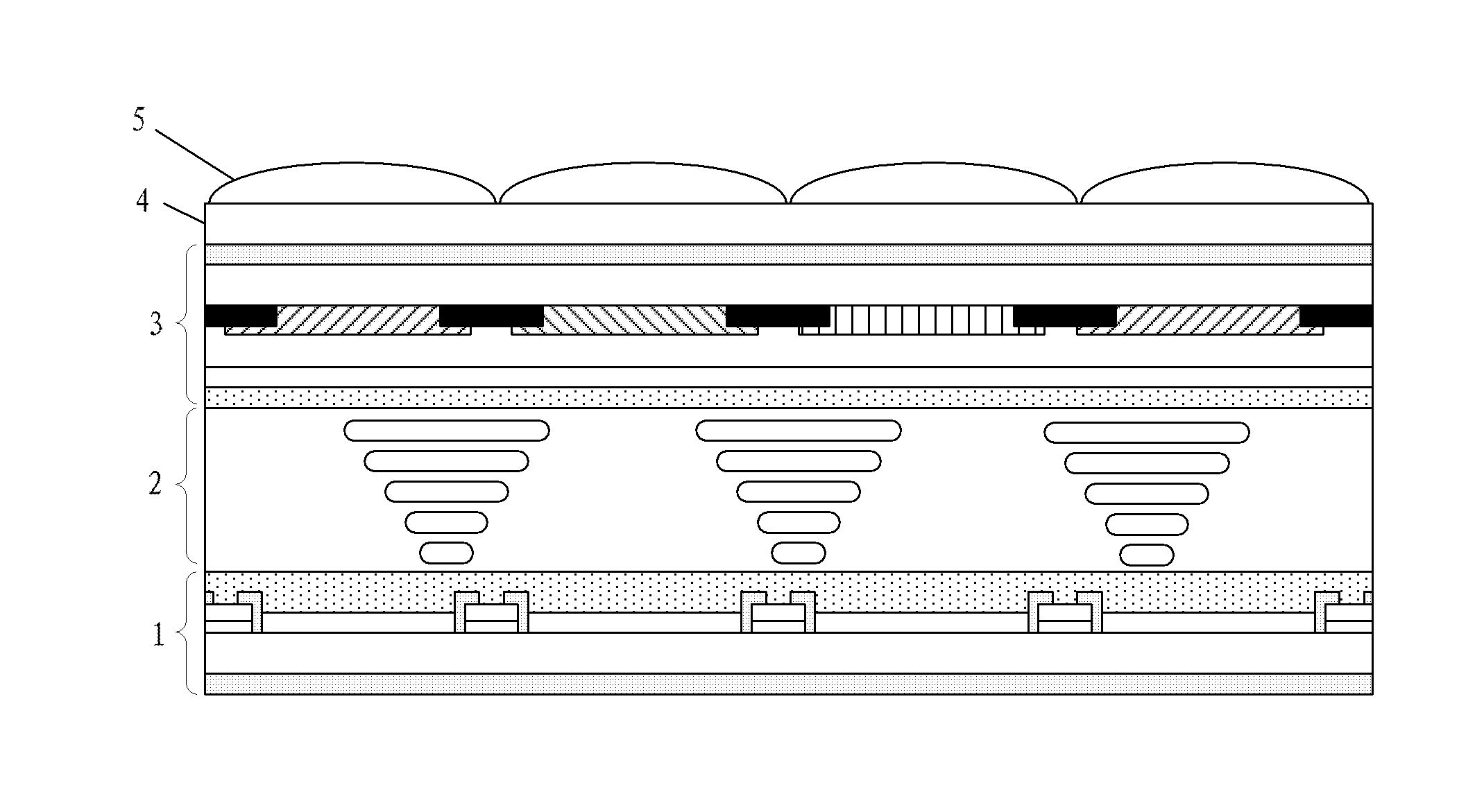
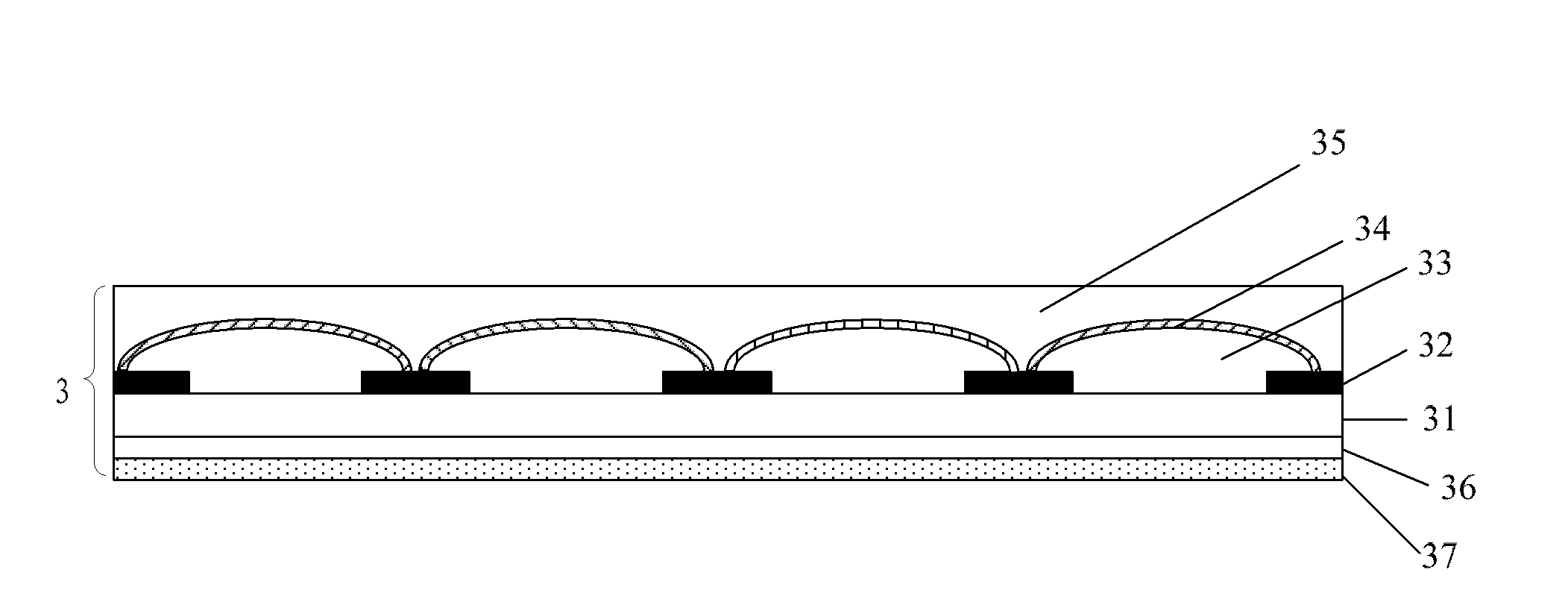
[0083] In Embodiment 1, the color filter layer in the color filter of the prior art is replaced by a colorless lenticular lens, and a colored film layer is formed on the achromatic lenticular lens, so that the light from the backlight is transmitted through After passing through the colorless lenticular lens and the colored film layer, a colored 3D image can be presented.
[0084] refer to image 3 , the color filter 3 of the embodiment of the present invention specifically includes:
[0085] Substrate 31;
[0086] A black matrix 32 formed on one side of the substrate 31;
[0087] A colorless lenticular lens 33 formed between the black matrices 32;
[0088] A colored film layer 34 formed on the colorless lenticular lens 33;
[0089] A transparent flat layer 35 formed on the colored film layer;
[0090] A transparent electrode layer 36 is formed on the other side of the substrate.
[0091] Wherein, the substrate 31 may be a glass substrate or a quartz substrate. The colo...
Embodiment 2
[0107] Embodiment 2 is to directly form a colorless lenticular lens and a transparent flat layer on the other side of the substrate of the color filter in the prior art, so that the light of the backlight is transmitted through the color filter layer and the color filter in the color filter. After the above-mentioned colorless lenticular lens is used, a colored 3D image can be presented.
[0108] refer to Figure 5 , the color filter 3 of the embodiment of the present invention specifically includes:
[0109] Substrate 31;
[0110] A colorless lenticular lens 33 formed on one side of the substrate 31;
[0111] A transparent flat layer 35 formed on the colorless lenticular lens 33;
[0112] A black matrix 32 formed on the other side of the substrate 31;
[0113] A color filter layer 38 formed between the black matrix 32;
[0114] a transparent flat layer 39 formed on the color filter layer 38;
[0115] The transparent electrode layer 36 formed on the transparent flat laye...
Embodiment 3
[0133] The difference between embodiment 3 and embodiment 1 is that the color lenticular lens is directly arranged in the color filter, so that after the light from the backlight passes through the color lenticular lens, a colored 3D image can be presented.
[0134] refer to Figure 7 , the color filter 3 of the embodiment of the present invention specifically includes:
[0135] Substrate 31;
[0136] A black matrix 32 formed on one side of the substrate 31;
[0137] A colored lenticular lens 40 formed between the black matrices 32;
[0138] A transparent flat layer 35 formed on the colored lenticular lens 40;
[0139] A transparent electrode layer 36 is formed on the other side of the substrate 31 .
[0140] Wherein, the substrate 31 may be a glass substrate or a quartz substrate. The colored lenticular lenses 40 are arranged at intervals in the black matrix 32, corresponding to different sub-pixel regions, and the colored lenticular lenses 40 can be red lenticular lense...
PUM
 Abstract
Description
Claims
Application Information