
Photoelectric Tracker Receive Control Circuit Synchronized with Absolute Time

A photoelectric tracker, receiving control technology, applied in the direction of control using feedback, can solve the problems of asynchronous, no absolute time code, etc., to achieve the effect of reducing the burden, high accuracy and stability, and improving real-time control and processing capabilities

Active Publication Date: 2011-12-21
CHINA NORTH IND NO 205 RES INST
View PDF6 Cites 10 Cited by
  • Summary
  • Abstract
  • Description
  • Claims
  • Application Information

AI Technical Summary

Problems solved by technology

At present, the W20ms external synchronization signal received by the photoelectric tracker is generated by the timing circuit of the weapon system, which is not synchronized with the absolute time, and there is no absolute time code. Transmit the absolute time, second pulse, and microsecond pulse signal output by the timer to the photoelectric tracker, so that all parts of the photoelectric tracker work synchronously with the absolute time, obtain the position data of the target under absolute time, and solve the problem of space-time measurement of the target , to achieve precise strikes on the target

Method used


Image

  • Photoelectric Tracker Receive Control Circuit Synchronized with Absolute Time
  • Photoelectric Tracker Receive Control Circuit Synchronized with Absolute Time
  • Photoelectric Tracker Receive Control Circuit Synchronized with Absolute Time

Examples


Embodiment Construction

[0015] The present invention will be further described in detail below in conjunction with the accompanying drawings and preferred embodiments.

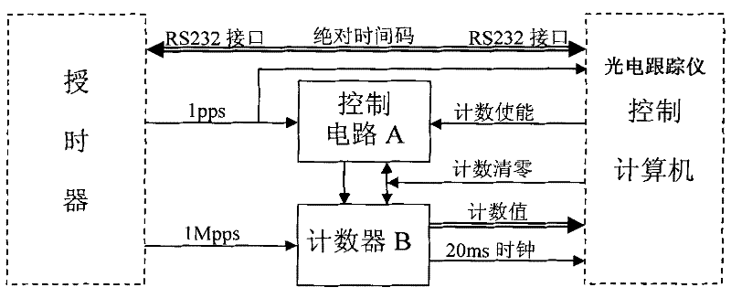
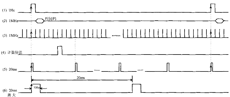
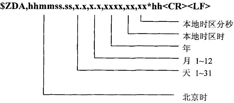
[0016] as figure 1 As shown, the synchronous receiving control circuit provided by the preferred embodiment of the present invention includes a control circuit A composed of first and second D flip-flops and an AND gate circuit, a counter B and a receiving control software package embedded in the photoelectric tracker control computer . Control circuit A and counter B receive the second pulse signal and the microsecond pulse signal output by the timer correspondingly (see figure 2 1st and 3rd signals in ). The control computer of the photoelectric tracker is connected with the Beidou or GPS timer through the RS232 serial port, and the receiving control software package receives the absolute time code output by the timer (see figure 2 The second signal in ) and synthesize it with the counting signal output by counter B, so that t...


PUM


Abstract

The invention discloses a receiving control circuit synchronized with absolute time of a photoelectric tracer. When receiving control software arranged on a control computer of the photoelectric tracer receives a second pulse and an absolute time code of a big dipper or a GPS (Global Positioning System) time service device, the receiving control software immediately transmits an effective enabling signal to the control circuit so as to control a counter to count microsecond impulse signals output by the time service device at next second pulse signal; and the receiving control software is used for calculating absolute time data corresponding to a second pulse and synthesizing the time data with a counting signal to obtain an absolute chronology of the photoelectric tracer. According to the receiving control circuit disclosed by the invention, the problem that various parts of the photoelectric tracer and the absolute chronology synchronously work is solved, thereby data acquired by ofthe photoelectric tracer during a live ammunition practice test can be compared with theoretical ballistic data, and missile launching can be monitored in real time and safely controlled. The receiving control circuit is simple and high in precision and stability and easy to realize; and the time for taking the control computer to acquire data is short.

Description

technical field [0001] The invention belongs to the technical field of synchronous control, and mainly relates to a synchronous receiving control circuit for a photoelectric tracker, in particular to a receiving control circuit when the photoelectric tracker is absolutely synchronous. Background technique [0002] The development of future weapon systems requires absolute time and synchronization with absolute time. Absolute time is also called Universal Coordinated Time, which is Beijing time in my country. The acquisition of absolute time is generated by receiving navigation satellite signals through the Beidou or GPS timer, outputting signals such as second pulses and microsecond pulses, and at the same time outputting absolute time codes at the rising edge of each second pulse through the RS232 serial port. The accuracy and stability are very high, reaching the level of picoseconds. [0003] Photoelectric trackers have multiple photodetectors, such as laser range finder...

Claims


Application Information

Patent Timeline
IPC IPC(8): G05D3/12
Inventor 刘建平陆培国王虎梁晓东郝利锋王世林刘汉平芦峰王超李志宇杨永安刘国栋
Owner CHINA NORTH IND NO 205 RES INST
Learn More