
High-power light emitting diode (LED) driving circuit

An LED driving, high-power technology, applied in the circuit layout of electric lamps, electric light sources, lighting devices, etc., can solve the problems of unstable switching oscillation, unstable output current, and inability to work, and achieve stable current, high stability, and cost. bottom effect

Inactive Publication Date: 2011-12-21
NANJING COLLEGE OF CHEM TECH
View PDF1 Cites 12 Cited by
  • Summary
  • Abstract
  • Description
  • Claims
  • Application Information

AI Technical Summary

Problems solved by technology

Common circuit faults are: the output current is unstable;

Method used


Image

  • High-power light emitting diode (LED) driving circuit
  • High-power light emitting diode (LED) driving circuit
  • High-power light emitting diode (LED) driving circuit

Examples


Embodiment Construction

[0022] The present invention will be further described below in conjunction with accompanying drawing. The following examples are only used to illustrate the technical solution of the present invention more clearly, but not to limit the protection scope of the present invention.

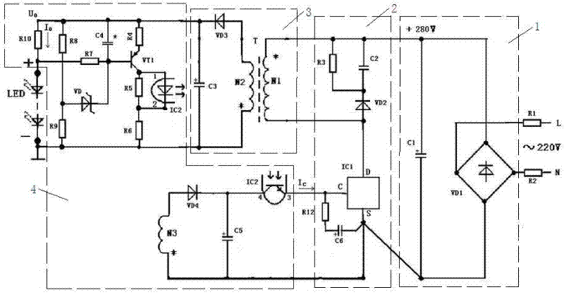
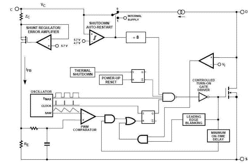
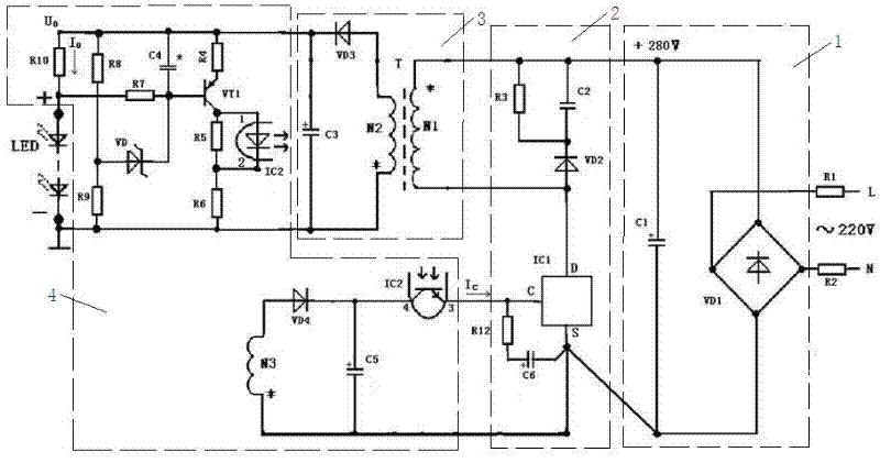
[0023] Such as figure 1 As shown, a high-power LED drive circuit is a typical single-ended flyback switching circuit, and the operating frequency has been internally set to 100KHZ. It includes a rectifier module 1 for rectifying the input AC power, a drive module 2 connected to the rectifier module 1 at one end, a transformer module 3 and a light source module 4 respectively connected to the other two ends of the drive module 2 . The driving module 4 includes a monolithic integrated switch circuit IC1. In this embodiment, the monolithic integrated switch circuit IC1 selects a triode whose model is TOP224Y. The AC 220V voltage is input, and the drive module 2 outputs a switching constant current cir...


PUM


Abstract

The invention discloses a high-power light emitting diode (LED) driving circuit, which is characterized by comprising a rectification module, a driving module, a voltage transformation module and a light source module, wherein the rectification module is used for rectifying input alternating current; one end of the driving module is connected with the rectification module; and the voltage transformation module and the light source module are connected with the other two ends of the driving module. The high-power LED driving circuit is simple in structure, low in power consumption, low in cost and high in stability and provides stable current. The high-power LED driving circuit is provided with an optocoupler feedback loop; the change of output current is small, namely 0.41 to 0.44A within a wide input voltage range from 150 to 250V and a wide LED load changing range (the output voltage range is from 11.4 to 31.5V when 1-3 LED(s) is / are connected in series), the constant current precision reaches + / -5 percent, and the requirement of an LED for power supply can be completely met.

Description

technical field [0001] The invention relates to a semiconductor integrated circuit, in particular to a high-power LED driving circuit. Background technique [0002] Since its birth, LED has developed at a rate of 20 times the brightness every 10 years and reduced the price to 1 / 100 of the original. With the invention of new materials and the improvement of light efficiency, the power and luminous flux of a single LED light source are also increasing rapidly. The rapid development of LED technology makes the application of LED in lighting engineering more and more extensive. For high-power LED lighting circuits, no matter what kind of power supply, it is impossible to directly supply power to the LED. If you want to use LED as a lighting source, you must solve the problem of power drive. [0003] The temperature coefficient of the PN junction of the LED is negative, and the barrier potential of the LED decreases when the temperature rises. Therefore, the LED cannot be dir...

Claims


Application Information

Patent Timeline
Patent Type & Authority Applications(China)
IPC IPC(8): H05B37/02
Inventor 石艳红张祖鹰
Owner NANJING COLLEGE OF CHEM TECH
Learn More