
A pile foundation quality detection method and device thereof

A quality inspection method and pile foundation technology, which can be applied in basic structure engineering, basic structure testing, construction, etc., can solve the problems of affecting the reliability of test results, high cost, weak reflected signal, etc., and achieve high-precision pile foundation without loss of quality. Effectiveness of detection and reliability improvement

Inactive Publication Date: 2011-12-28
朱德兵
View PDF1 Cites 28 Cited by
  • Summary
  • Abstract
  • Description
  • Claims
  • Application Information

AI Technical Summary

Problems solved by technology

[0003] In the former, there is almost no relative change between the transmitting and receiving position of the elastic wave and the internal defect position of the pile foundation, and it is difficult to identify and grasp the reflected wave generated by the defect from a single detection curve, especially for long piles, the lower reflected signal is inherently very weak; at the same time , since the high-energy direct wave cannot be effectively suppressed or filtered out, it also directly affects the identification of defect reflection signals, especially the extraction and interpretation of shallow reflection signals
The second method has the advantages of intuitive detection data and relatively reliable results, but the detection tube must be pre-embedded during the pouring construction, which will affect the construction progress and quality; because the pre-embedded detection tube often has abnormal phenomena such as bending, it will also affect the detection The reliability of the results; at the same time, this detection method has a long cycle and relatively high cost
[0004] Due to the limitations of the observed data in the "single hammer single geophone" operation mode in pile foundation detection, the existing record information extraction algorithm is completely based on one-dimensional digital signal processing, and the information extraction and identification capabilities are very limited

Method used

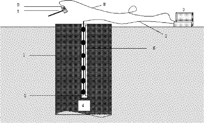

Image

  • A pile foundation quality detection method and device thereof
  • A pile foundation quality detection method and device thereof
  • A pile foundation quality detection method and device thereof

Examples


Embodiment Construction

[0020] The present invention will be further described below in conjunction with the accompanying drawings and specific embodiments.

[0021] see figure 1 , the device for realizing the pile foundation quality detection method, the detector string 1 formed by 4 to 16 miniature speed or acceleration sensors with an interval of 5 to 15 cm, the output signal of the detector string 1 passes through the first signal cable 2 and multiple channels The synchronous elastic wave acquisition instrument 3 is connected, and the trigger 9 carried by the hammering source 7 is connected with the multi-channel synchronous elastic wave acquisition instrument 3 through the second signal cable 8; A wall-attaching device in which the wave detector is closely attached to the wall of the detection hole 5 . Adhesive device is machinery, magnetoelectric type or air bag 6, water bag.

[0022] The pile foundation quality inspection method comprises a plurality of miniature speed or acceleration sensor...


PUM


Abstract

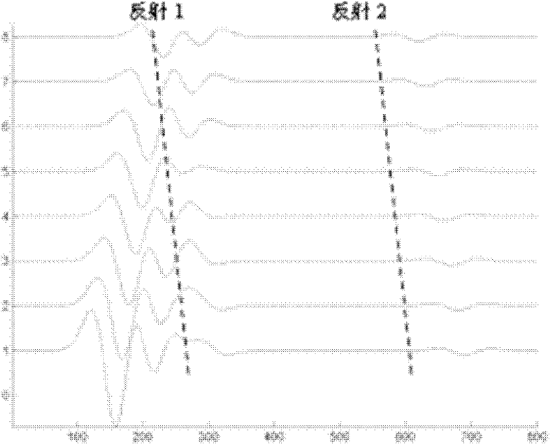
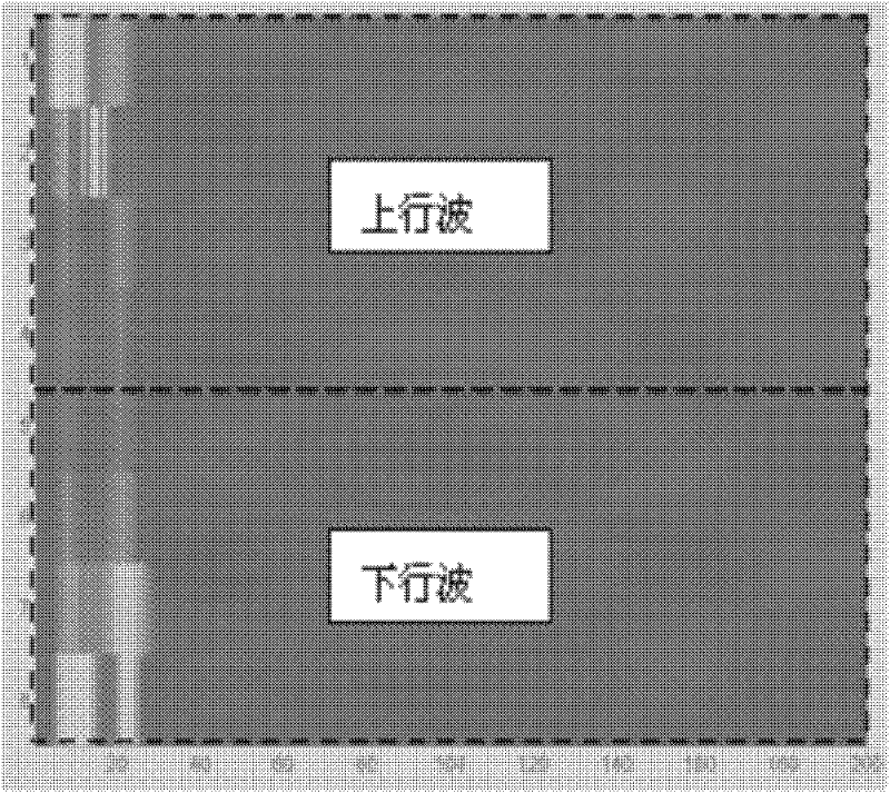
The invention discloses a pile foundation quality detection method and device. The method comprises: connecting an output signal of an about-10cm interval geophone string formed by micro-speed or acceleration sensors with a multichannel synchronization elastic wave acquirer (3) by a signal cable (2); removing laitance on a pile head of a pile foundation (4), cleaning the pile head, and forming a detection hole (5) axially parallel to the pile foundation at the center of the pile head by a drilling machine, wherein the hole diameter is about 50cm and the hole depth is about 1m; placing the geophone string along the detection hole, and enabling geophones to be tightly attached on the wall of the detection hole by a machine or an inflation air bag (6); exciting elastic waves in modes of hammering (7) on the pile head and the like, recording elastic wave response signals by the multichannel synchronization elastic wave acquirer (3) through the signal cable, and repeatedly hammering to form signal superposition; and performing travelling wave separation on upward travelling waves and downward travelling waves in multichannel elastic wave response signals, pressing or filtering the downward travelling waves, reserving the upward travelling waves for reflecting defect reflected signals of the lower part of the pile foundation, and performing excursion superposition according to the correlation of the defect reflected upward travelling signals to form reflected signals excited and received on the pile top surface, thus obtaining positions and properties of defects at the lower part of the pile foundation. In the detection method, reliability of interpreting and extracting defect reflected signals in pile foundation detection is improved by comprehensive technologies of multiple excitation signal superposition, multi-sensor signal travelling wave separation, correlated reflected signal excursion superposition and the like, thus improving reliability of detection results.

Description

technical field [0001] The invention relates to a pile foundation quality detection method, and also relates to a device for realizing the pile foundation quality detection method. technical background [0002] There are two existing pile foundation detection methods, one is to fix the elastic wave sensor on the pile head, and at the same time excite the elastic wave at the pile head, and analyze the location of hidden dangers in the lower part of the pile foundation according to the arrival time and waveform characteristics of the elastic wave reflection signal One is to pre-embed 2 to 4 parallel detection tubes during the pouring process of the pile foundation, and then detect and analyze the quality of the pile foundation through the elastic wave transmission signal between the holes. [0003] In the former, there is almost no relative change between the transmitting and receiving position of the elastic wave and the internal defect position of the pile foundation, and it...

Claims


Application Information

Patent Timeline
IPC IPC(8): E02D33/00
Inventor 朱德兵
Owner 朱德兵
Learn More