An optical engine with variable field of view

An optical engine and engine technology, applied in the direction of engine components, machines/engines, mechanical equipment, etc., can solve problems such as inability to meet multiple measurement requirements at the same time, and achieve the effect of high mechanical strength

Active Publication Date: 2011-12-28
TIANJIN UNIV
View PDF8 Cites 18 Cited by
  • Summary
  • Abstract
  • Description
  • Claims
  • Application Information

AI Technical Summary

Problems solved by technology

To solve the problem that one optical engine cannot meet multiple measurement requirements at the same time, through the integrated design and adaptive design of the cylinder liner, the configurability of various measurement requirements can be realized

Method used


Image

  • An optical engine with variable field of view
  • An optical engine with variable field of view
  • An optical engine with variable field of view

Examples


Embodiment

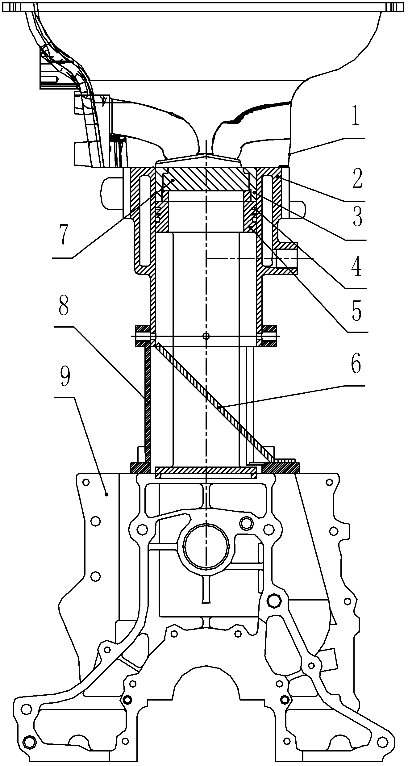
[0046] The piston of a certain cylinder of the prototype machine is threadedly connected with the extended piston 5, and the top of the extended piston 5 is provided with a glass groove for placing a circular flat quartz glass 7. Glass 7 is fixed on the top of extension piston 5. At the same time, the length of the extended piston is controlled to ensure the compression ratio of the engine. Have piston ring groove 4 on the extension piston 5, be used for installing gas ring and lubricating graphite ring, gas ring can guarantee the tightness of engine, and the installation of graphite ring guarantees the lubrication of lengthening piston and cylinder liner.

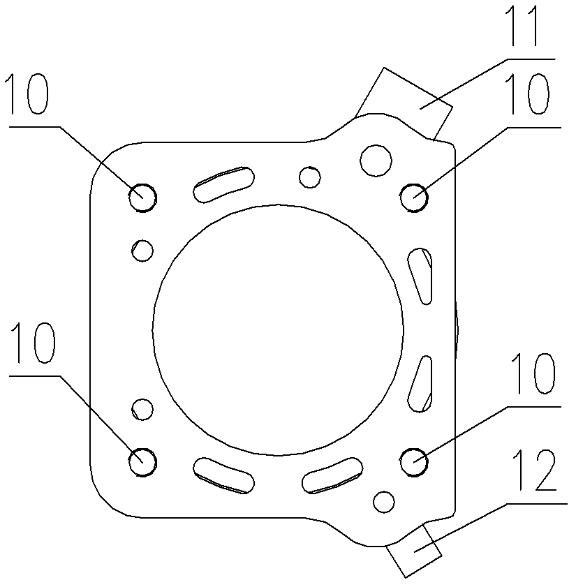
[0047] The outer sleeve of the extended piston is provided with a metal lengthened cylinder liner 2, and there are 4 threaded holes 10 on the metal lengthened cylinder liner 2, such as Figure 1-2 As shown, the metal extended cylinder liner 2 and the cylinder head 1 are connected by four cylinder head bolts, and the metal...


PUM


Abstract

The invention discloses an optical engine with variable view field. The optical engine comprises a cylinder body of the engine, a cylinder cover and a lengthened piston, wherein the middle part of the lengthened piston has hollowed structure, a reflector is placed in the space of the hollowed structure, and a piece of circular planar quartz glass is arranged at the top of the lengthened piston; aguide base is fixed at the upper part of the cylinder body, and cylinder sleeves are fixed between the guide base and the cylinder cover; the number of the cylinder sleeves is three, the heights of the three cylinder sleeves are consistent, and the connecting mode between each cylinder sleeve and the cylinder cover at the upper part of the cylinder sleeve and between the cylinder sleeve and the guide base at the lower part of the cylinder sleeve and the geometric dimension of the cylinder sleeves are the same to ensure interchangeability of the three cylinder sleeves; and the three cylinder sleeves are respectively a metal lengthened cylinder sleeve, an annular quartz glass cylinder sleeve and a planar mosaic glass cylinder sleeve, and variable view field of the optical engine is realizedby alternately using the three cylinder sleeves. The problem that a conventional optical engine cannot meet multiple measurement requirements at the same time is solved, and various measurement requirements are met by integrated design and adaptive design of the cylinder sleeves.

Description

technical field [0001] The invention relates to the combustion diagnosis of an automobile engine, in particular to an optical engine. Background technique [0002] Optical engines can use optical visualization technology to diagnose and analyze the state of the cylinder, and provide guidance for engine combustion design and combustion optimization. At present, many internal combustion engine research institutions at home and abroad have established corresponding optical engine visualization measurement platforms, which have played an important role in engine combustion theory and engine design. [0003] The main purpose of the optical engine is to open a visualization window on the engine under conditions as close as possible to the actual engine operation to obtain the information in the cylinder when the engine is running. After decades of development, the extended piston engine has become a typical optical engine mode. [0004] Anders Hultqvist, Magnus Christensen, Lund...

Claims


Application Information

Patent Timeline
Patent Type & Authority Applications(China)
IPC IPC(8): F02F3/00F02F1/00
Inventor 谢辉宋东先邹庆武
Owner TIANJIN UNIV
Why Eureka
Try Eureka