Yuan Zhirong's paper "Full Attitude Error Compensation of Three-axis Magnetic Heading Sensor" proposes to divide the compass error into orthogonal error, zero position and sensitivity error to compensate separately. This method has high compensation accuracy, but a non-magnetic turntable is required in the compensation process , and the computer is required to automatically measure the maximum and minimum values of the X and Y axis sensor outputs when the compass rotates one revolution, the calibration process is more complicated, and the equipment requirements are higher; And Shao Tingting, Ma Jiancang's paper "Study on the
Compensation Algorithm for Tilt and Error of the Electronic
Compass" uses the
least squares method to compensate the electronic compass. The size of the sampled data will have a great
impact on the fitting results. If the amount of data is too small, the
compensation effect will not be good. If the amount of data is too large, the fitting performance will deteriorate; Research on Error
Correction Method" and Qi Zhang, Liang-shui Lei, Jiang Fan, Song Liu's paper "Autocalibration of a magnetic compass without heading reference" proposed a compensation method based on the
ellipse assumption error model, because the
ellipse assumption model is only based on the experiment According to experience, the
compensation effect is not very ideal due to the lack of theoretical proof; Chao Min, Jiang Dongfang, and Wen Caihong’s paper "Magnetic
Compass Error Analysis and Calibration" uses analytical methods to establish a more accurate model of the magnetic direction measurement
system, and the electronic compass Compensation is carried out under horizontal conditions, but there are many parameters to be identified during the compensation process (up to 9), and the results show that the
compensation effect is similar to the
ellipse hypothesis model; Hao Zhenhai, Huang Shengguo's paper "Composite Heading
System Based on Differential Magnetic
Compass" A design scheme of "Differential Magnetic Compass" (DMC, Differential Magnetic Compasses) is proposed, which uses the combination of two identical magnetic compasses to judge whether the
system has low-frequency interference. If there is no low-frequency interference in the system, the magnetic compass is used Navigation mode, if low-frequency interference occurs in the system, the system will switch to the
gyroscope navigation mode
This scheme does not substantially improve the measurement accuracy of the magnetic compass, and the navigation scheme is composed of a
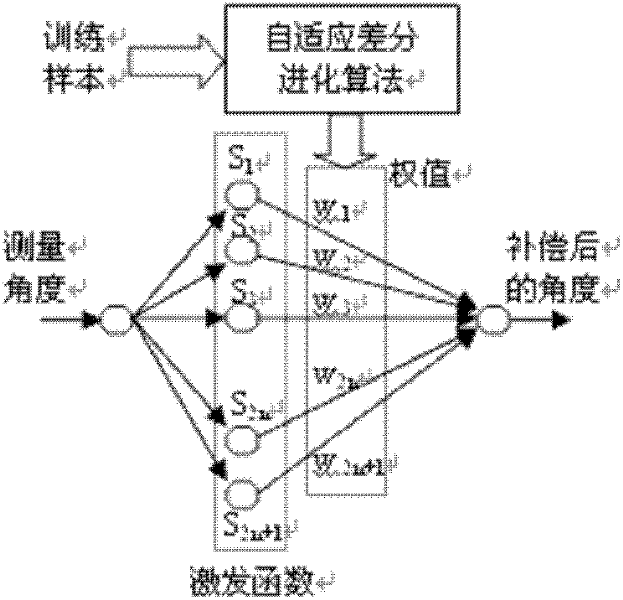
gyroscope and multiple magnetic compasses, which will greatly increase the cost; Wang Lu, Zhao Zhong et al. The BP neural network establishes an error model and uses the LM learning
algorithm to
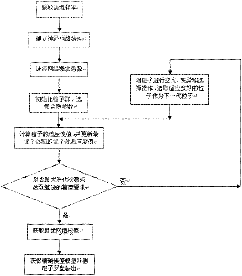
train the network. This method does not require average sampling within 0° to 360°. It has the characteristics that the neural network can approximate the function with arbitrary precision and has high compensation accuracy. The convergence speed of the network is slow, and the setting of the initial value of the weight needs to be very careful, and it is easy to fall into a local minimum
[0004] To sum up, the main methods for calibrating the electronic compass at present include the least square method, ellipse
hypothesis method, BP neural
network method, etc. These methods may have cumbersome calibration steps, high requirements for the equipment required for calibration, or calibration accuracy. not enough

