Velocity Planning Method of Double Nurbs Tool Trajectory in Five-axis NC Machining

A tool path and speed planning technology, applied in the field of CNC machine tools, can solve problems such as affecting the efficiency of processing, lack of real-time, affecting the quality of the processed surface, etc., to achieve the effect of improving processing efficiency, ensuring processing accuracy, and high computing efficiency

Active Publication Date: 2011-12-28
SHANGHAI JIAO TONG UNIV +1
View PDF5 Cites 46 Cited by
  • Summary
  • Abstract
  • Description
  • Claims
  • Application Information

AI Technical Summary

Problems solved by technology

In order to improve the machining accuracy, it is necessary to use very small line segments and circular arcs to approach the curved surface, which will cause a series of additional problems: firstly, many small line segments will cause ordinary acceleration and deceleration of the machine tool during processing. On the one hand, , the sharp fluctuation of the speed will seriously affect the quality of the machined surface; on the other hand, it is difficult for the machine tool to reach the expected feed rate during the entire machining process, which affects the efficiency of machining
In the existing technologies for five-axis linkage equidistant double NURBS interpolation, the speed planning method of constant feed speed or constant feed acceleration is adopted, without considering the interpolation accuracy, material removal rate and servo capability of each axis of the machine tool. comprehensive constraints
However, the speed planning method of constant feed speed or constant feed acceleration does not change the feed speed adaptively in real time according to the geometric characteristics of the tool path and the servo capabilities of each axis of the machine tool. In order to ensure the machining accuracy, only For the entire tool path, if a constant and conservative feed rate and feed acceleration are adopted, the processing efficiency cannot be improved, so the advantages of double NURBS interpolation cannot be fully utilized

Method used


Image

  • Velocity Planning Method of Double Nurbs Tool Trajectory in Five-axis NC Machining
  • Velocity Planning Method of Double Nurbs Tool Trajectory in Five-axis NC Machining
  • Velocity Planning Method of Double Nurbs Tool Trajectory in Five-axis NC Machining

Examples


Embodiment 1

[0039] This embodiment is based on the dynamic constraints of the five-axis machine tool for the speed planning method of the dual NURBS curve tool trajectory, which is divided into two steps:

[0040] 1. Establishment of comprehensive constraints for dual NURBS curve interpolation based on the dynamic characteristics of a five-axis machine tool.

[0041] 1) Establish the tool speed distribution field model in the dual NURBS curve tool trajectory and solve the maximum feasible feed rate constraint determined by it.

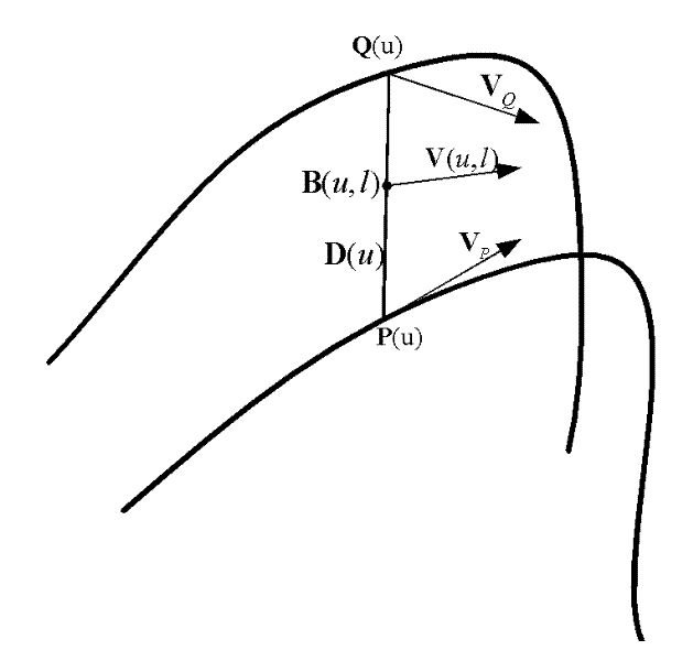
[0042] Such as figure 1 As shown, the double NURBS curve is an equidistant double NURBS tool path, P(u) represents the tool center point NURBS curve, Q(u) represents the tool axis point NURBS curve, and the point on the curve P(u) represents the tool position point, through The point connecting P(u) and Q(u) at the corresponding parameter indicates the direction of the tool axis, which is denoted as D(u), that is, D(u)=P(u)-Q(u).

[0043] in:

[0044] The tool ce...

Embodiment 2

[0075] First establish the tool velocity field distribution, record the NURBS curve of the tool center point as P(u), the tool axis point NURBS curve as Q(u), and the tool direction as D(u), then D(u)=P(u)- Q(u). Note that |D(u)|=H, then the unit vector of the tool direction can be expressed as Then the point on the tool axis can be expressed as B(u, l)=P(u)+lO(u), where l is the distance from the point on the tool axis to the center point of the tool. By deriving time on both sides of the equation, the velocity at any point on the tool axis can be found. By limiting the feed speed of the tool along the machining path, the speed of any point on the tool axis can be achieved first, and the resulting constraint is called the constraint of the tool speed field on the maximum feed speed.

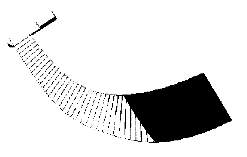
[0076] Next, establish the constraints of the tool scanning area on the feed rate. Firstly, establish the formula for the scanning area of ​​the tool axis:

[0077] S ...


PUM


Abstract

The invention discloses a NURBS (Non-Uniform Rational B-Splines) tool path speed planning method for five-axis numerical control machining. The method comprises the following steps of: 1, creating synthesized constraints oriented to double NURBS cure tool path route interpolation, synthesizing the constraints to solve a maximum speed and an acceleration of the tool in a moving process, and establishing a synthesized constraint space in a machine tool interpolation process; 2, performing bidirectional speed planning based on window scanning, taking the current speed as basis, scanning forwardsfrom a window start pint to a window tail end in a viable speed domain to obtain a feeding speed of a current period. The method ensures that the path is machined with the highest speed under a condition of meeting the requirements on servo capability and machining performance of the machine tool, and implements a high-quality and high-efficiency machining process.

Description

technical field [0001] The invention relates to a numerical control method in the technical field of numerical control machine tools, in particular to a speed planning method of dual NURBS tool paths for five-axis numerical control machining. Background technique [0002] The processing of curved surfaces, that is, the NC processing of parts with free-form surfaces and curved contours has been increasingly valued and widely used. For example, complex shape parts used in aerospace vehicles, automobile streamlined covers, mold cavities and steam turbine blades are typical representatives of parts with complex curves and surfaces. Small line segment interpolation based on discrete straight line segments and circular arcs is a traditional method used to process such complex curves and surfaces. In order to improve the machining accuracy, it is necessary to use very small line segments and circular arcs to approach the curved surface, which will cause a series of additional prob...

Claims


Application Information

Patent Timeline
Patent Type & Authority Applications(China)
IPC IPC(8): G05B19/41
Inventor 王宇晗冯景春石璟
Owner SHANGHAI JIAO TONG UNIV
Why Eureka
Try Eureka