Eureka AIR delivers breakthrough ideas for toughest innovation challenges, trusted by R&D personnel around the world.

Microwave frequency range combiner

A technology of microwave frequency band and combiner, which is applied in the direction of waveguide devices, circuits, electrical components, etc., can solve the problems of unbalanced insertion loss curve, high manufacturing cost, deterioration of combiner insertion loss, etc., and achieve port standing wave ratio Optimization, optimized VSWR performance, and overall performance optimization

Active Publication Date: 2011-12-28
COMBA TELECOM SYST (GUANGZHOU) LTD
View PDF4 Cites 6 Cited by
  • Summary
  • Abstract
  • Description
  • Claims
  • Application Information

AI Technical Summary

Problems solved by technology

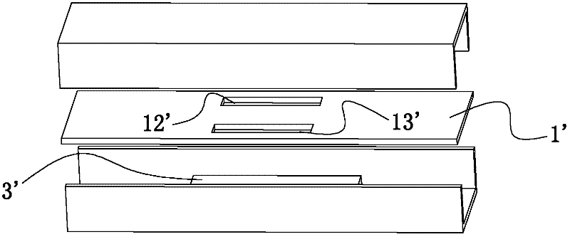
Such a combiner has a narrow frequency band, and the insertion loss curve is unbalanced in the frequency band, especially the standing wave ratio of the three ports deteriorates greatly
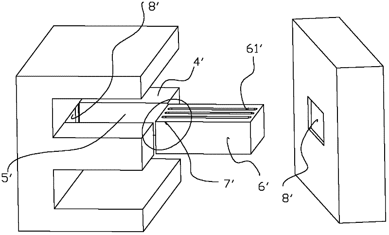
[0005] An improved scheme such as figure 2 As shown, the two waveguide cavities of the combiner and the partition 4' and the hole 5' in the middle of the partition 4' are integrally processed, and a gap hole 61' is placed at the middle long hole 5' of the partition 4' The metal block 6', the gap hole 61' provided on the metal block 6' and the long hole 5' in the middle of the partition plate 4' jointly constitute the coupling slot assembly 7' of the combiner. For such a combiner, It is difficult for the metal block 6' with the gap hole 61' to fully contact the left and right walls of the two waveguide cavities 8' of the combiner at the same time. The contact is not complete, and there will be gaps, resulting in the insertion loss of the combiner Deterioration, especially in the high-frequency band, correspondingly increases the requirements for machining accuracy, and its manufacturing cost is also high, which is not conducive to large-scale mass production

Method used


Image

  • Microwave frequency range combiner
  • Microwave frequency range combiner
  • Microwave frequency range combiner

Examples


Embodiment Construction

[0026] Below in conjunction with accompanying drawing and embodiment the present invention will be further described:

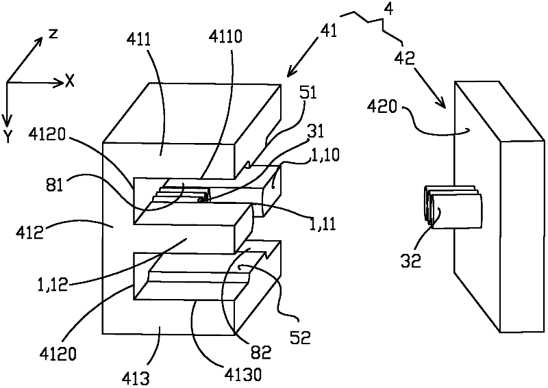
[0027] see image 3 , In the preferred embodiment of the present invention, the microwave band combiner is composed of a rectangular cavity 4, a coupling plate 1 and a plurality of metal columns 31, 32. For the convenience of description, define the longitudinal direction of the coupling plate 1, that is, the longitudinal direction of the rectangular cavity 4, as the global longitudinal direction Z, and define the width direction of the coupling plate 1, that is, the width direction of the rectangular cavity 4, as the global width direction X defines the thickness direction of the coupling plate 1 , that is, the thickness direction of the rectangular cavity 4 as the global thickness direction Y. The rectangular cavity 4 is integrated to form a longitudinal inner cavity jointly defined by four side inner walls 4110, 4120, 4130, 420, for the convenience of com...


PUM


Abstract

The invention discloses a microwave frequency range combiner which comprises a rectangular cavity and a coupling plate which divides the rectangular cavity into two waveguide cavities. A longitudinal direction of the coupling plate is defined as a global longitudinal direction, and a width direction of the coupling plate is defined as a global width direction. At a middle of the global longitudinal direction, the coupling plate is provided with an orifice to form two parts with a distance. Rectangular cavity inner walls at two sides of a global width direction of the orifice are provided with a plurality of metal cylinders which are perpendicular to the inner walls and are pressed against each other. A coupling gap is formed between the metal cylinders and the coupling plate and / or between two adjacent metal cylinders. The two waveguide cavities are provided with impedance matching devices. According to the microwave frequency range combiner, the metal cylinders and the orifice on the coupling plate form the coupling gap which is combined with echelonment matching devices in the waveguide cavities, so that adjustment is flexible and convenient, whatever a frequency bandwidth, coupling energy size or a balance degree in a frequency band has an absolute advantage, and performance is substantially improved.

Description

【Technical field】 [0001] The invention relates to a microwave passive device, in particular to a microwave frequency band combiner. 【Background technique】 [0002] Microwave communication is one of the commonly used wireless communication means in the world at present, and is widely used in data transmission, radio and television transmission, satellite communication, mobile communication and other fields. The combiner is an outdoor three-port network device for wireless transmission products, which connects the antenna and two outdoor units (ODU), that is, two transceiver channels share one antenna through the combiner. [0003] The combiner connects the antenna and two ODU units. Its existence will inevitably increase the insertion loss of the antenna and increase the standing wave ratio, thereby deteriorating the overall performance of the antenna. Therefore, the design of the combiner is to make the deterioration of the electrical performance of the combiner under worki...

Claims


Application Information

Patent Timeline
Patent Type & Authority Applications(China)
IPC IPC(8): H01P1/213
Inventor 王岩吴知航罗辉叶军伟刘素芹潘军唐荣
Owner COMBA TELECOM SYST (GUANGZHOU) LTD
Why Eureka
Eureka Blog
Learn More