Photovoltaic millimeter wave power synthesis circuit

A power synthesizing circuit, a technology of optically generating millimeter waves, applied in the directions of power amplifiers, high-frequency amplifiers, etc., can solve the problems of inability to increase the cut-off frequency of photodetectors, limit the response speed of photodetectors, system linearity and high cost, and improve the Power synthesis efficiency, improving circuit standing wave ratio, satisfying the effect of high power and large bandwidth

Inactive Publication Date: 2012-06-27
NINGBO UNIV
View PDF2 Cites 4 Cited by
  • Summary
  • Abstract
  • Description
  • Claims
  • Application Information

AI Technical Summary

Problems solved by technology

The ultra-wideband wireless access network composed of the radio-over-fiber (ROF) system realizes the long-distance connection between the central processing station and the base station through the optical fiber, and realizes the wireless coverage within tens of meters through the millimeter-wave system. Its working mode is mainly : The central processing station modulates the data and the millimeter-wave signal using an external modulation technology based on optical carrier suppression (OCS) to obtain a double-peak optical signal. The double-peak optical signal is beaten to recover the modulated millimeter-wave signal, and then the modulated millimeter-wave signal is amplified by the millimeter-wave power amplifier and radiated by the transmitting antenna; however, the millimeter-wave power amplifier is not only expensive, but also has serious problems. It is difficult to meet the linearity requirements of complex modulation methods with high spectral efficiency, and it is also not conducive to the goal of low-cost and maintenance-free base stations; therefore, a method using erbium-doped fiber amplifiers to transmit signals in After the optical domain is amplified, it is directly sent to the photodetector, and the photodetector recovers the beat frequency of the received double-peak optical signal to obtain a solution that the millimeter wave signal is directly radiated by the transmitting antenna. This solution solves the problem of system linearity and cost High problem, but higher requirements for photodetectors, which require photodetectors to have high response speed and high output power capability
In order to meet the requirements of photodetectors for response speed and output power, photodetectors generally use a photogenerated millimeter-wave power synthesis circuit connected by a single photodiode according to an artificial transmission line structure. At the same time, the power is limited by the cut-off frequency of the photodiode itself, and the cut-off frequency of the photodetector cannot be increased, thus limiting the response speed of the photodetector.

Method used


Image

  • Photovoltaic millimeter wave power synthesis circuit
  • Photovoltaic millimeter wave power synthesis circuit
  • Photovoltaic millimeter wave power synthesis circuit

Examples


Embodiment 1

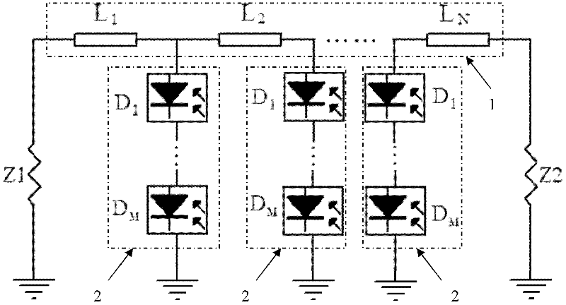
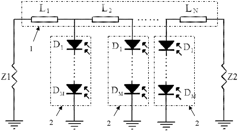
[0030] Embodiment one: if figure 2 As shown, an optically-generated millimeter-wave power synthesis circuit includes a first load Z1, a second load Z2 and a microstrip line group 1. The microstrip line group 1 is composed of N sections of microstrip lines in series. The microstrip line group 1 One end of the first load Z1 is connected to one end of the first load Z1, the other end of the microstrip line group 1 is connected to one end of the second load Z2, the other end of the first load Z1 and the other end of the second load Z2 are grounded, and the microstrip line group 1 A photoelectric conversion module 2 is connected to the common connection end of each adjacent two sections of microstrip lines, and each photoelectric conversion module 2 is grounded. The photoelectric conversion module 2 is formed by serially connecting M photoelectric conversion units. The photoelectric conversion unit is one A photodiode, the cathodes and anodes of M photoelectric conversion units ar...

Embodiment 2

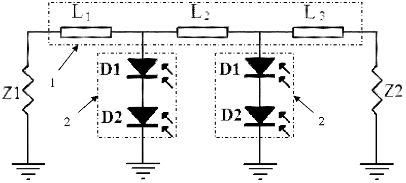
[0031] Embodiment two: if image 3 As shown, an optically-generated millimeter-wave power synthesis circuit includes a first load Z1, a second load Z2 and a microstrip line group 1. The microstrip line group 1 is composed of three sections of microstrip lines in series. One end of the first load Z1 is connected to one end of the first load Z1, the other end of the microstrip line group 1 is connected to one end of the second load Z2, the other end of the first load Z1 and the other end of the second load Z2 are grounded, and the microstrip line group 1 A photoelectric conversion module 2 is connected to the common connection end of each adjacent two sections of microstrip lines, and each photoelectric conversion module 2 is grounded. The photoelectric conversion module 2 is composed of two photoelectric conversion units in series, and the photoelectric conversion unit is Photodiodes, the cathodes and anodes of the two photoelectric conversion units are connected in series, and...

Embodiment 3

[0033] Embodiment three: as Figure 6As shown, an optical-generated millimeter-wave power synthesis circuit includes a first load Z1, a second load Z2 and a microstrip line group 1. The microstrip line group 1 is composed of four sections of microstrip lines in series. One end of the first load Z1 is connected to one end of the first load Z1, the other end of the microstrip line group 1 is connected to one end of the second load Z2, the other end of the first load Z1 and the other end of the second load Z2 are grounded, and the microstrip line group 1 A photoelectric conversion module 2 is connected to the common connection ends of every two adjacent microstrip lines, and each photoelectric conversion module 2 is grounded. Photodiode, the cathode and anode of the two photoelectric conversion units are connected in series, the first photoelectric conversion unit D in the photoelectric conversion module 2 1 The anode of the anode is connected to the microstrip line group 1, and...


PUM


Abstract

The invention discloses a photovoltaic millimeter wave power synthesis circuit, which comprises a first load, a second load, a micro-strip line group and photoelectric conversion modules, wherein the micro-strip line group is formed by sequentially connecting N micro-strip lines in series; one end of the micro-strip group is connected to one end of the first load, while the other end of the micro-strip line group is connected with one end of the second load; both the other end of the first load and the other end of the second load are grounded; a common connection end of every two adjacent micro-strip lines in the micro-strip line group is connected with one photoelectric conversion module; each photoelectric conversion module is grounded; and each photoelectric conversion module is formed by sequentially connecting M photoelectric conversion units in series, wherein the N is greater than or equal to 3, and the M is greater than or equal to 2. The photovoltaic millimeter wave power synthesis circuit has the advantages that not only photoelectric conversion output power is increased but also output cutoff frequency is increased, so that work bandwidth is widened.

Description

technical field [0001] The invention relates to a power synthesis circuit, in particular to an optical-generated millimeter wave power synthesis circuit. Background technique [0002] Optical fiber communication has the characteristics of low loss and high bandwidth. Radio over Fiber (ROF) technology is a newly developed wireless access technology that combines optical fiber communication and wireless communication to meet the needs of high-speed and large-capacity wireless communication. The ultra-wideband wireless access network composed of the radio-over-fiber (ROF) system realizes the long-distance connection between the central processing station and the base station through the optical fiber, and realizes the wireless coverage within tens of meters through the millimeter-wave system. Its working mode is mainly : The central processing station modulates the data and the millimeter-wave signal using an external modulation technology based on optical carrier suppression ...

Claims


Application Information

Patent Timeline
Patent Type & Authority Applications(China)
IPC IPC(8): H03F3/189H03F3/20
Inventor 文化锋刘太君聂秋华徐铁峰叶焱应祥岳
Owner NINGBO UNIV
Why Eureka
Try Eureka