
Simple polarization tracker for communication in motion

A technology of polarization tracking and communication in motion, applied in the field of satellite communication, can solve the problems of many parts, high machining accuracy, and cumbersome assembly process, and achieve the effect of reducing accuracy and cost, facilitating machining and assembly, and reducing machining difficulty.

Pending Publication Date: 2019-12-17
航天恒星空间技术应用有限公司 +1
View PDF2 Cites 4 Cited by
  • Summary
  • Abstract
  • Description
  • Claims
  • Application Information

AI Technical Summary

Problems solved by technology

The new polarization tracker has the following problems and disadvantages: 1. The connection between the upper and lower straight arm waveguides of the orthogonal mode coupler needs to rely on multiple waveguide matching blocks and the coupling that runs through the two side walls of the waveguide cavity. The joint effect of the needles is complex in structure and is not conducive to the isolation of the two arms; 2. The U-shaped probe needs to be formed after three times of bending, and the bent probe needs to meet high processing accuracy, which increases the cost of the mold and manufacturing difficulty, affecting the pass rate of the probe
The polarization tracker has the following problems and disadvantages: 1. The polarization tracker has multiple gears and bearing structures, many parts and complex structures, the assembly process is cumbersome, and the cost is high; 2. The output of the polarization tracker The two arms are in different directions; 3. The stepper motor drives the L-shaped waveguide rotary joint to drive the rotary orthogonal mode coupler to rotate, so as to realize the seamless tracking of the linear polarization signal. There are many relatively moving parts during work, making the pole After the tracker works for a long time, it is easy to cause wear and tear between the various parts, which affects the transmission of electromagnetic signals and the tracking effect

Method used


Image

  • Simple polarization tracker for communication in motion
  • Simple polarization tracker for communication in motion
  • Simple polarization tracker for communication in motion

Examples


Embodiment 1

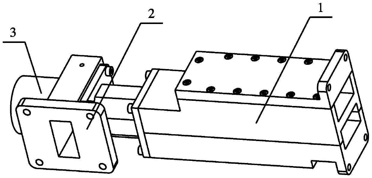
[0062] Such as figure 1 As shown, this embodiment provides a simple polarization tracker for communication in motion, including a quadrature mode coupler 1 , a polarization selector 2 , and a stepping motor 3 .

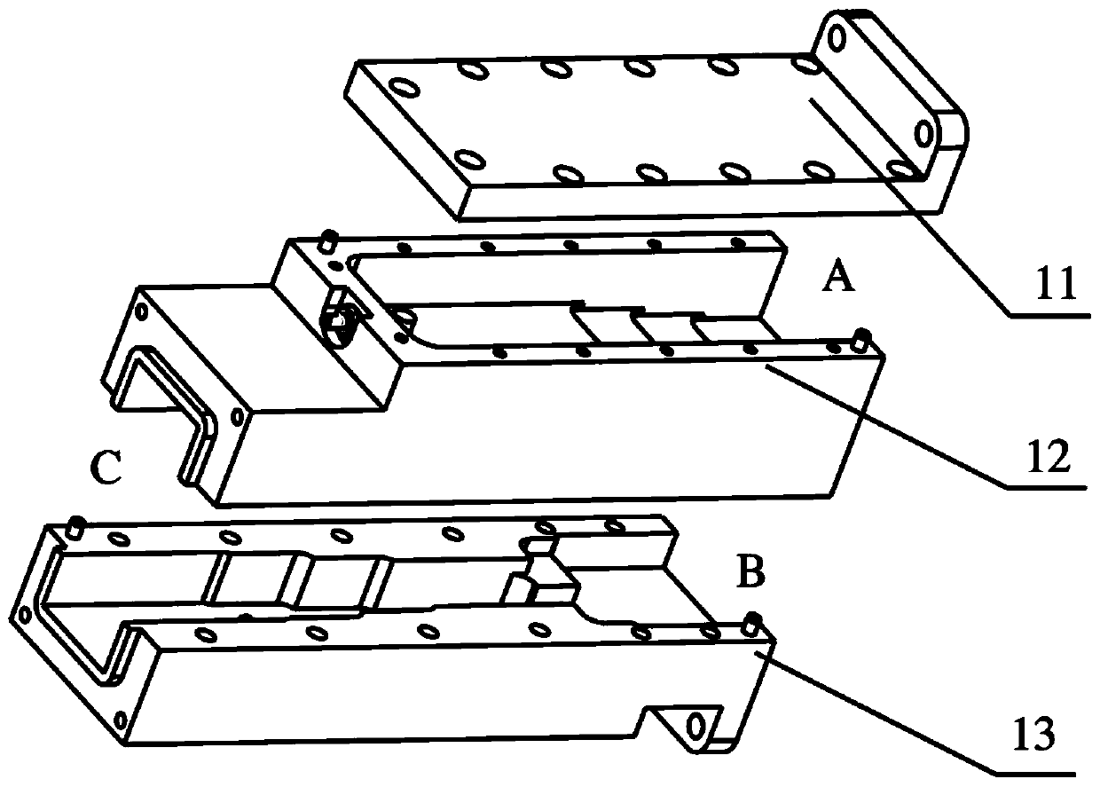
[0063] Among them, such as figure 2 As shown, the orthogonal mode coupler 1 includes an upper waveguide structure block 11 , a middle waveguide structure block 12 , and a lower waveguide structure block 13 from top to bottom. The upper waveguide structure block 11 , the middle waveguide structure block 12 and the lower waveguide structure block 13 are connected by bolts to form a whole, forming a three-port network. The upper waveguide structure block 11 is connected with the middle waveguide structure block 12 to form a first channel with one end open. The first channel has an electromagnetic wave signal input port A, and a first rectangular waveguide cavity is provided in the first channel. The middle waveguide structure block 12 is connected with the lower waveg...


PUM


Abstract

The invention provides a simple polarization tracker for communication in motion. The tracker comprises an orthogonal mode coupler, a polarization selector and a stepping motor, wherein the orthogonalmode coupler sequentially comprises an upper waveguide structure block, a middle waveguide structure block and a lower waveguide structure block from top to bottom, the upper waveguide structure block, the middle waveguide structure block and the lower waveguide structure block are connected to form a first channel and a second channel which are parallel to each other, a through hole is formed inthe middle waveguide structure block and close to the center of a bottom surface of a tail end of an inner cavity of a first rectangular waveguide, a cylindrical dielectric block is arranged in the through hole, a first probe is arranged in the center of the cylindrical dielectric block, the first probe is a cylindrical metal probe, a polarization torsion structure is arranged close to an input end of an inner cavity of a second rectangular waveguide, a medium rotor is arranged in the polarization selector, a second probe is arranged at one end of the medium rotor, and the second probe is a Z-shaped cylindrical metal probe. The simple polarization tracker has advantages of simple structure, convenient machining and assembling and low cost.

Description

technical field [0001] The invention relates to the technical field of satellite communication, in particular to a simple polarization tracker for communication in motion. Background technique [0002] Mobile communication is the abbreviation of "moving satellite ground station communication system". The specific objects of the mobile communication include vehicles, ships, airplanes and other mobile carriers. Mobile Communication can realize the real-time tracking of the satellite platform during the movement of the mobile carrier, and uninterrupted transmission of multimedia information including images and sounds. At present, most of the Ku and C frequency band satellites adopt the linear polarization mode. During the movement of the mobile carrier relative to the geostationary satellite, on the one hand, the maximum gain direction of the antenna must always be aligned with the satellite; The linear polarization direction can be dynamically adjusted to ensure that it matc...

Claims


Application Information

Patent Timeline
IPC IPC(8): H01Q15/24H01P1/16
CPCH01Q15/24H01P1/161
Inventor 宿孟
Owner 航天恒星空间技术应用有限公司
Learn More