Radiation unit of antenna and antenna

A radiation unit and antenna technology, which is applied to antenna unit combinations with different polarization directions, radiation element structure forms, antennas and other directions, can solve problems such as poor consistency, poor consistency, and increased overall weight and volume of the antenna, and achieve compensation Decrease in antenna performance, increase in cost and process, and effect of improving cross-polarization ratio

Active Publication Date: 2019-10-11
SHENZHEN SAMSUNG COMM TECH RES +1
View PDF6 Cites 4 Cited by
  • Summary
  • Abstract
  • Description
  • Claims
  • Application Information

AI Technical Summary

Problems solved by technology

[0003] Among them, the heat-cold shrinkage deformation and weight of the die-casting vibrator have always been a serious constraint problem, and the die-casting vibrator needs to be manufactured with mold opening, which has low precision and poor consistency
[0004] The bandwidth of the printed vibrator is narrow. In order to widen the bandwidth, it is often necessary to add metal pillars at the end corners of the vibrator, which not only increases the manufacturing process and cost, but also has poor accuracy and poor consistency.
[0005] On the premise of reducing the size of the PCB patch vibrator, the isolation needs to be sacrificed, and the isolation needs to be increased, which leads to an increase in the overall weight and volume of the antenna.
[0006] Although the combined board gold vibrator is light in weight, the assembly process is complicated and it is not easy to achieve surface mount technology (SMT) assembly
[0007] It can be seen that the existing various antenna elements cannot solve the problems of large size, medium weight, narrow bandwidth, and poor isolation at the same time, so they cannot adapt to 5G-MIMO (fifth generation mobile communication technology - multiple input multiple output antenna) requirements

Method used


Image

  • Radiation unit of antenna and antenna
  • Radiation unit of antenna and antenna
  • Radiation unit of antenna and antenna

Examples


Embodiment Construction

[0037] In order to make the object, technical solution and advantages of the present invention clearer, the present invention will be further described in detail below with reference to the accompanying drawings and examples.

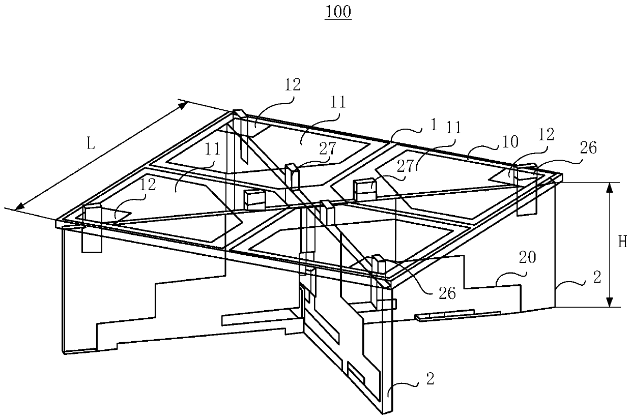
[0038] In order to support the reduction of the volume of the antenna, the following embodiments intend to reduce the thickness of the antenna by reducing the height of the radiator, so as to make the antenna thinner. At the same time, the following embodiments also provide compensation for the antenna performance loss caused by the height reduction of the radiator. Preferably, the compensation can at least enable the antenna to meet the performance requirements of the base station or the micro base station.

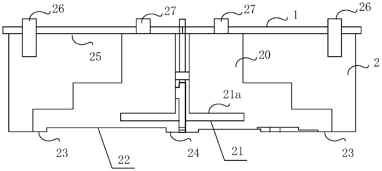
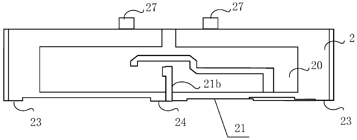
[0039] figure 1 is a perspective view of a radiation unit in an embodiment. figure 2 and image 3 are plan views of two embodiments of the dipole balun circuit board. Such as Figure 1 to Figure 3 As shown, in one embodiment, a radiation unit...


PUM


Abstract

The invention discloses a radiation unit of an antenna, and the radiation unit comprises an oscillator radiation circuit board which is provided with oscillator radiation arms arranged in pairs in a printed manner, wherein the width of each oscillator radiation arm is less than a half of the wavelength; an oscillator balun circuit board which is used for supporting the oscillator radiation circuitboard, wherein an oscillator balun is printed on the oscillator balun circuit board, the height of the oscillator balun is less than one fifth of the wavelength, and the oscillator balun is providedwith at least one first slot. Based on the invention, in particular for a 5G-MIMO large-array base station and a micro base station, the radiation unit can improve the overall performance of antennassuch as bandwidth, isolation, gain, cross polarization and the like as a whole, and meanwhile, the size of the antenna cannot be reduced with relatively small performance loss.

Description

technical field [0001] The present invention relates to antenna technology, in particular to a radiation unit of the antenna and an antenna using the radiation unit. Background technique [0002] Antenna vibrator is the most widely used form in the field of base station antennas, accounting for more than 80% of base stations. Most of the existing antenna vibrators include the following forms: die-cast vibrator, printed vibrator, PCB (printed circuit board) chip vibrator, composite board gold vibrator, etc. Wherein, the height of the radiator (also called "vibrator", including the dipole radiation arm and dipole balun) used in the radiation unit of the existing antenna is usually set to a quarter wavelength, so the volume of the vibrator is relatively large. [0003] Among them, the heat-cold shrinkage deformation and weight of the die-casting vibrator have always been a serious constraint problem, and the die-casting vibrator needs to be manufactured with mold opening, whic...

Claims


Application Information

Patent Timeline
Patent Type & Authority Applications(China)
IPC IPC(8): H01Q1/36H01Q1/38H01Q1/50H01Q19/10
CPCH01Q1/36H01Q1/38H01Q1/50H01Q19/10H01Q21/26H01Q1/246H01Q1/48
Inventor 伍爱国洪富文陈卓
Owner SHENZHEN SAMSUNG COMM TECH RES
Why Eureka
Try Eureka