An induction antenna, an electronic tag and an electronic tag reader
An induction antenna and electronic tag technology, applied in the field of communication, can solve problems such as poor non-contact performance, low transaction success rate, and short transaction distance, and achieve the effects of improving quality, reducing interference, and increasing energy
- Summary
- Abstract
- Description
- Claims
- Application Information
AI Technical Summary
Problems solved by technology
Method used
Image
Examples
Embodiment 1
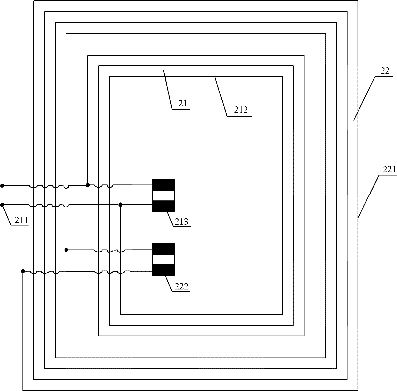
[0038] see figure 2 , is a schematic structural diagram of the induction antenna in Embodiment 1 of the present invention, the induction antenna may include an induction coil 21 and a relay coil 22, wherein:
[0039] The induction coil 21 includes an input terminal pair 211 and a first coil 212;
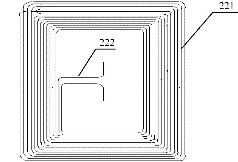
[0040] The relay coil 22 includes at least one second coil 221, and the second coil 221 is connected end to end to form a closed coil;
[0041] The relay coil 22 is spatially separated from the induction coil 21 by a preset distance, and is electromagnetically inductively coupled with the induction coil 21 . The preset distance between the relay coil 22 and the induction coil 21 in space is specifically: the minimum distance between the relay coil 22 and the induction coil 21 only needs to ensure that the two do not touch each other. As long as the maximum distance between them is ensured that the relay coil 22 is located in the magnetic field generated by the induction coil 21 . ...
Embodiment 2
[0051] see Figure 4A , is a schematic structural diagram of the electronic tag in Embodiment 2 of the present invention, the electronic tag includes a chip 40 and an inductive antenna, and the inductive antenna includes: a working coil 41 and a relay coil 42, wherein:
[0052] The working coil 41 includes an input terminal pair 411 and a first coil 412, and the input terminal pair 411 is connected to the chip 40;
[0053] The relay coil 42 includes at least one second coil 421, and the second coil 421 is connected end to end to form a closed coil;
[0054] The relay coil 42 is spatially separated from the working coil 41 by a preset distance, and is electromagnetically inductively coupled with the working coil 41 . In Embodiment 2 of the present invention, the preset distance between the relay coil 42 and the working coil 41 in space is as follows: the minimum distance between the relay coil 42 and the working coil 41 only needs to ensure that the two do not touch each other...
Embodiment 3
[0066] see Figure 7A , is a schematic structural diagram of the electronic tag reader-writer in Embodiment 3 of the present invention, the electronic tag reader-writer may include a body 70, an induction antenna provided with a working coil 71 and a relay coil 72, wherein:
[0067] The working coil 71 includes an input terminal pair 711 and a first wire 712 turns, the input terminal pair 711 is connected to the body 70;
[0068] The relay coil 72 includes at least one second coil 721 , and the second coils 721 are connected end to end to form a closed coil.
[0069] The working coil 71 is used to receive the signal sent by the electronic tag through the relay coil 72, and to send the signal to the electronic tag through the relay coil 72; the relay coil 72 is used to pre-receive, adjust and enhance the signal sent by the electronic tag After obtaining the first signal, and sending the first signal to the working coil; and, the relay coil 72 is used to obtain the second signa...
PUM
 Abstract
Description
Claims
Application Information
 - R&D
- Intellectual Property
- Life Sciences
- Materials
- Tech Scout
- Unparalleled Data Quality
- Higher Quality Content
- 60% Fewer Hallucinations
Browse by: Latest US Patents, China's latest patents, Technical Efficacy Thesaurus, Application Domain, Technology Topic, Popular Technical Reports.
© 2025 PatSnap. All rights reserved.Legal|Privacy policy|Modern Slavery Act Transparency Statement|Sitemap|About US| Contact US: help@patsnap.com


