Cold-pressed terminal

A technology of cold-pressed terminals and free ends, which is applied in the direction of multi-core cable end parts, connections where permanent deformation works, etc., can solve the problems of inconvenient operation and the difficulty of cold-pressed terminals to meet the requirements of compact structure, and achieves space-saving, easy-to-use Installation and maintenance, effect of short radial length

Inactive Publication Date: 2011-12-28
SIEMENS AG
View PDF8 Cites 2 Cited by
  • Summary
  • Abstract
  • Description
  • Claims
  • Application Information

AI Technical Summary

Problems solved by technology

However, the length of this cold-pressed terminal 80 along its axis is relatively long. In electrical equipment with a narrow space, it is difficult for a cold-pressed terminal of this size to

Method used


Image

  • Cold-pressed terminal
  • Cold-pressed terminal
  • Cold-pressed terminal

Examples


Example Embodiment

[0028] In order to have a clearer understanding of the technical features, objectives and effects of the invention, specific embodiments of the invention will now be described with reference to the accompanying drawings. In each figure, the same reference numerals represent the same parts.
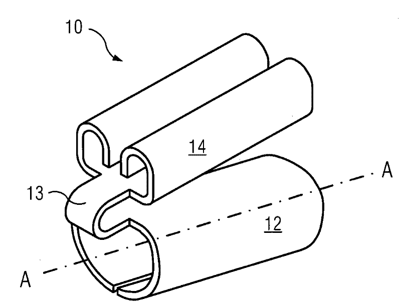
[0029] figure 2 An embodiment of the cold-pressed terminal 10 of the present invention is described. As shown in the figure, the cold-pressed terminal 10 includes a cable assembly portion 12 and a connector assembly portion 14. The cable assembly portion 12 has an axis AA indicating the cable insertion direction, and the connector assembly portion 14 is superimposed on the cable assembly portion 12 in a direction perpendicular to the axial direction AA. The angle between the above-mentioned connector assembly portion 14 and the cable assembly portion 12 can be determined within a range of less than 90 degrees according to actual manufacturing requirements and installation requirements.

[003...


PUM


Abstract

The invention discloses a cold pressed terminal which comprises a cable assembly part and a connection piece assembly part, wherein the cable assembly part is provided with a first axial direction for the insertion of a cable; and the connection piece assembly part and the cable assembly part are overlapped at the direction vertical to the first axial direction. The cold pressed terminal has the advantages of shorter radial length, smaller occupied space and compact structure, can enable greater current to pass, and is also easy to install and maintain.

Description

technical field [0001] The invention relates to a cold-pressed terminal, in particular to a cold-pressed terminal with short length and convenient manufacture. Background technique [0002] In the fields of communication and electricity, there are two main types of terminal blocks, one is the terminal connected to the cable by hot pressing (that is, by hot-melt welding, etc.), and the other is by external force (by crimping pliers) etc.) The terminal connected to the cable is usually called a cold-pressed terminal. [0003] figure 1 A cold-press terminal 80 commonly used in the prior art is described, including a cable fitting part 82 and a connector fitting part 84 , and the cable fitting part 82 and the connector fitting part 84 are sequentially connected in the direction of the axis AA. When in use, the connecting cable (or signal line, etc.) 70 can be inserted into the crimp terminal 80 along the axis AA, and then the cable assembly part 82 and the connector assembly p...

Claims


Application Information

Patent Timeline
IPC IPC(8): H01R11/11H01R4/18H01R4/20
Inventor 张登科周志平方晓兰
Owner SIEMENS AG
Why Eureka
Try Eureka