driven car axle

An automobile shaft and driven technology, applied in the field of automobile shafts, can solve the problems of high structural space requirements, complex braking equipment, insufficient braking effect, etc., and achieve the effect of reducing the structure size and small installation space

Inactive Publication Date: 2011-12-28
SIEMENS AG
View PDF3 Cites 3 Cited by
  • Summary
  • Abstract
  • Description
  • Claims
  • Application Information

AI Technical Summary

Problems solved by technology

[0004] The use of conventional brake systems in conventional vehicles with hybrid drives, usually hydraulic brake systems, which are complex and have a high installation space requirement and require frequent maintenance
Although the electric machine can also generate a certain braking effect in generator operation, this braking effect is not sufficient at higher speeds, so a conventional braking device must be additionally provided, which can be realized, for example, as hydraulic disc brake

Method used


Image

  • driven car axle
  • driven car axle

Examples


Embodiment Construction

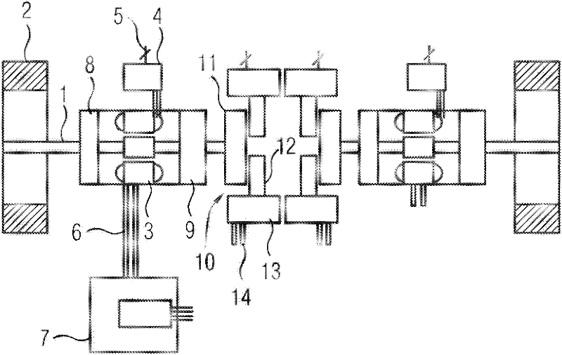
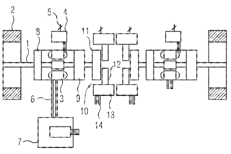
[0020] The motor vehicle 1 is symmetrically constructed and has at its ends each a wheel 2 which can be driven by means of an electric motor 3 . A control device (controller) 4 is provided for controlling and regulating the electric motor 3 , which is connected on the one hand to the electric motor 3 and on the other hand to the electrical connection 5 . The electric machine 3 has a cooling connection 6 which is connected via a heat exchanger to a schematically indicated heat store 7 , so that the electric machine 3 can be cooled while the heat store 7 is heated. The heat accumulator 7 can be used to regulate the temperature of the interior of the hybrid vehicle.

[0021] A transmission 8 is arranged between the wheels 2 and the electric machine 3 , by means of which the rotational speed of the electric machine 3 can be increased and the torque reduced. The transmission 8 is designed in such a way that the electric machine 3 runs in an optimum rotational speed range.

[0022...


PUM


Abstract

The invention relates to a driven vehicle axle, which is coupled or can be coupled to an internal combustion engine and / or at least one electric machine that optionally can be operated as an engine or generator and which comprises a brake device having an eddy current brake (10).

Description

technical field [0001] The invention relates to a driven vehicle axle which is coupled or can be coupled to an internal combustion engine and / or at least one electric machine which can optionally be operated as a motor or generator and which has a braking device. Background technique [0002] Such driven axles are used in hybrid or pure electric vehicles. A hybrid vehicle is a vehicle that is powered by at least one electric motor and at least one other engine. Currently, a hybrid vehicle mainly has an internal combustion engine and an electric motor. [0003] Hybrid electric vehicles, also known as hybrid vehicles, can be configured in different ways. A distinction is generally made between hybrid vehicles with series hybrid drives, parallel hybrid drives and vehicles with power split devices. In a series hybrid drive, the combustion engine drives an electric generator to generate electricity for charging an electric energy storage or directly drives an electric motor. ...

Claims


Application Information

Patent Timeline
Patent Type & Authority Applications(China)
IPC IPC(8): B60L7/28B60L11/12B60L11/14B60W10/18B60L50/10B60L50/15B60L50/16F16D65/28
CPCB60K6/52B60K2007/0092B60L7/28Y02T10/70B60L11/123B60L11/14Y02T10/6217B60L2220/44Y02T10/7077Y02T10/6265B60K1/02B60K7/0007B60K17/043B60K6/46B60L50/16B60L50/61Y02T10/62Y02T10/7072B60K6/22F16D65/28
Inventor 马库斯.克洛普齐格海因兹-沃纳.纽米勒
Owner SIEMENS AG
Why Eureka
Try Eureka