Image encoding method and image decoding method

An image decoding and image coding technology, which is applied in the field of image coding and image decoding, can solve the problems of increased processing capacity, reduced prediction performance, and lack of evaluation target blocks and surrounding blocks, etc., to achieve suppression of increase, suppression of coding distortion, and suppression of processing volume effect

Inactive Publication Date: 2011-12-28
PANASONIC CORP
View PDF2 Cites 13 Cited by
  • Summary
  • Abstract
  • Description
  • Claims
  • Application Information

AI Technical Summary

Problems solved by technology

Through the above method, although the prediction efficiency of prediction mode estimation can be improved, but the processing load increases
Furthermore, even with such a method, since the relationship between the target block and the surrounding blocks is not evaluated, when the features of the surrounding blocks are different from the features of the image of the target block, similar to the method of the H.264 / AVC standard, it is possible to predict reduced performance

Method used


Image

  • Image encoding method and image decoding method
  • Image encoding method and image decoding method
  • Image encoding method and image decoding method

Examples


Embodiment 1

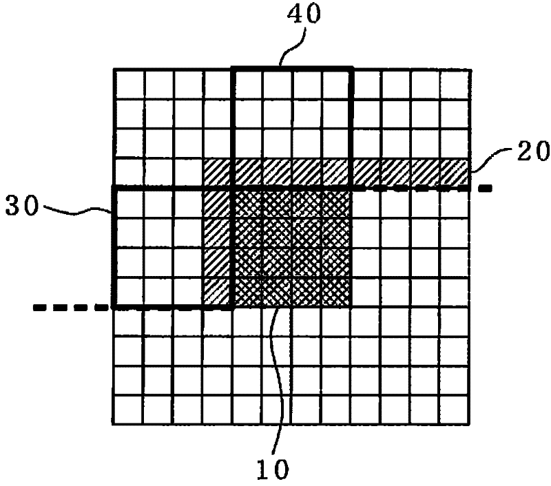
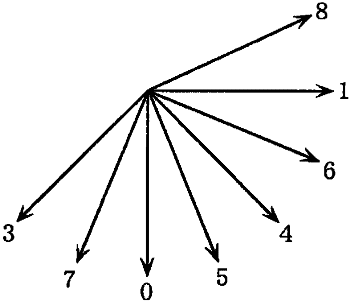
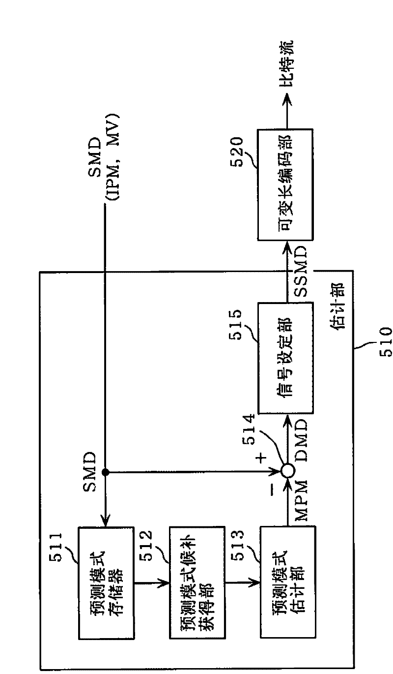
[0101] The image encoding device of this embodiment is characterized in that when encoding image and video data, it detects edges included in surrounding blocks located around the target block, and reduces a plurality of prediction modes based on the detected edges. As for the number of candidates, one prediction mode is determined from the reduced number of prediction mode candidates as the estimated prediction mode.

[0102] Furthermore, the image decoding device of this embodiment is characterized in that, when decoding the encoded image and video data, edges included in surrounding blocks are detected, and a plurality of prediction mode candidates are reduced based on the detected edges. , determine a prediction mode from the reduced number of prediction mode candidates as an estimated prediction mode, and restore the prediction block based on the determined estimated prediction mode and the mode information sent from the encoder side. Generated prediction model.

[0103]...

Embodiment 2

[0346] The processing shown in the above-mentioned embodiments can be easily executed in an independent computer system by recording a program for realizing the configuration of the image coding method or the image decoding method shown in the above-mentioned embodiments in a recording medium. The recording medium may be a magnetic disk, an optical disk, a magneto-optical disk, an IC card, a semiconductor, or the like, as long as the program can be recorded.

[0347] Here, an application example of the image coding method and image decoding method shown in the above-mentioned embodiments and a system using the application example will be described.

[0348] Figure 20 It is a diagram showing the overall configuration of a content supply system ex100 that realizes a content distribution service. The area for providing communication services is divided into desired sizes, and base stations ex106 to ex110 serving as fixed wireless stations are installed in each cell.

[0349] T...

Embodiment 3

[0385] The image coding method and device, image decoding method and device shown in the above-mentioned embodiments can typically be realized by an LSI as an integrated circuit. As an example, Figure 27 The configuration of LSIex500 fabricated as one chip is shown. The LSI ex500 includes elements ex501 to ex509 to be described below, and the respective elements are connected via a bus ex510. The power supply circuit unit ex505 is activated to be in an operable state by supplying electric power to each unit when the power is turned on.

[0386] For example, when encoding processing is performed, the LSI ex500 receives an input of an AV signal from a microphone ex117, a camera ex113, etc. through an AV input / output ex509 under the control of a control unit ex501 including a CPU ex502, a memory controller ex503, and a stream controller ex504. The input AV signal is temporarily stored in an external memory ex511 such as SDRAM. According to the control of the control unit ex50...


PUM


Abstract

In order to achieve higher coding efficiency, suppress coding artifacts, and not to need a large computing amount, an image and video data are coded. Provided is an image coding method of coding image data on a block-by-block basis, and the method includes: coding a current block according to a prediction based on a selected prediction mode (S101); determining an estimated prediction mode from among candidate prediction modes; and outputting the coded current block and mode information for reconstructing the selected prediction mode (S108). The determining includes: detecting an edge (S103); reducing the candidate prediction modes in number based on the detected edge (S105); determining the estimated prediction mode from among the candidate prediction modes reduced in number (S106); and generating the mode information based on the estimated prediction mode and the selected prediction mode (S107).

Description

technical field [0001] The present invention relates to an image encoding method for compressing and encoding images and video data with better encoding efficiency, an image decoding method for decoding compressed and encoded images and video data, and an image encoding device and image corresponding to these methods decoding device. Background technique [0002] The number of applications for video conferencing via the Internet, digital video broadcasting, and streaming including video content, for example for video-on-demand services, mainly by means of the transmission of video information, is constantly increasing. When video data is transmitted or recorded, a considerable amount of data is transmitted through a conventional transmission path with a limited bandwidth, or is stored in a conventional storage medium with a limited data capacity. In order to transmit and store video information on conventional transmission channels and storage media, it is essential to comp...

Claims


Application Information

Patent Timeline
Patent Type & Authority Applications(China)
IPC IPC(8): H04N7/32
CPCH04N19/00781H04N19/00278H04N19/00157H04N19/00036H04N19/176H04N19/61H04N19/109H04N19/14H04N19/103H04N19/50
Inventor 笹井寿郎西孝启柴原阳司V·德吕容
Owner PANASONIC CORP
Why Eureka
Try Eureka