Annular supersonic velocity spray pipe and design method thereof

A design method and supersonic technology, applied in the direction of injection devices, injection devices, etc., can solve the problem of different gas acceleration characteristics, the inability to guarantee the uniformity of the flow field Mach number and flow direction angle, and the difficulty in solving wave suppression and viscosity correction in the supersonic region, etc. question

Active Publication Date: 2012-01-04
NAT UNIV OF DEFENSE TECH
View PDF3 Cites 18 Cited by
  • Summary
  • Abstract
  • Description
  • Claims
  • Application Information

AI Technical Summary

Problems solved by technology

This geometrically complex relationship makes the expansion characteristics of the annular flow channel different from that of two-dimensional or circular pipes, so the acceleration characteristics of the gas are also different. This particularity of geometry and flow structure brings certain limitations to the design method. difficulty
Although there are a variety of relatively mature two-dimensional or axisymmetric nozzle design methods, which can achieve high outlet flow field quality, the existing methods cannot be directly extended to the design of the annular nozzle profile curve.
The main problems it faces include: 1. The existing flow models and empirical formulas are difficult to apply directly; Third, the correction of the boundary layer on the annular wall is also different from that of the axis

Method used


Image

  • Annular supersonic velocity spray pipe and design method thereof
  • Annular supersonic velocity spray pipe and design method thereof
  • Annular supersonic velocity spray pipe and design method thereof

Examples


Embodiment Construction

[0056] Hereinafter, the present invention will be described in detail with reference to the drawings and examples. It should be noted that, in the case of no conflict, the embodiments in the present application and the features in the embodiments can be combined with each other.

[0057] In the present invention, the subsonic section refers to the part where the flow velocity of the airflow is less than the speed of sound after entering the constriction section of the nozzle, and the subsonic section is also the transonic section, which refers to the junction between the airflow entering the supersonic state from the subsonic state, Generally, the Mach number in the subsonic section is less than 0.8, the Mach number in the subsonic section is between 0.8 and 1.2, and the Mach number in the supersonic section is greater than 1.2.

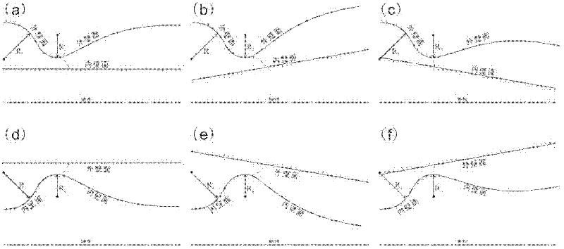
[0058] Such as figure 1 As shown, according to the annular supersonic nozzle design method of the present invention, first determine whether the in...


PUM


Abstract

The invention provides an annular supersonic velocity spray pipe and a design method thereof. The design method for the annular supersonic velocity spray pipe comprises the following steps of: predicting a flow field parameter in a transonic velocity segment area, and extracting an initial characteristic line from the flow field parameter; determining the mach number distribution of a supersonic velocity upright wall of the spray pipe according to design requirements; and determining a supersonic velocity curved wall molded surface of the spray pipe by a characteristic line method according to the initial characteristic line and the mach number distribution of the supersonic velocity upright wall. According to the design method for the annular supersonic velocity spray pipe, compression waves are not concentrated in a flow field of the designed annular supersonic velocity spray pipe, the distribution of the flow field parameter can be optimized according to actual application, and thequality of the flow field of the annular supersonic velocity spray pipe can be greatly improved. According to the annular supersonic velocity spray pipe, the design method for the annular supersonic velocity spray pipe is utilized.

Description

technical field [0001] The invention relates to the field of fluid power, in particular to an annular supersonic nozzle and a design method thereof. Background technique [0002] Supersonic nozzles are widely used in high-speed aircraft, rockets, supersonic wind tunnels, high-energy lasers, ejector vacuum pumps and other equipment. The quality of the nozzle flow field has an important impact on the performance of the equipment. Obtaining an appropriate nozzle wall curve through certain design techniques can greatly improve the quality of the nozzle flow field, improve equipment performance, and save research funds. The supersonic nozzle is generally composed of a constriction section and an expansion section. Driven by a certain pressure, the gas gradually accelerates in the constriction section and reaches the speed of sound near the throat, and then continues to accelerate in the expansion section until the required Mach number and flow are formed at the outlet. Supersoni...

Claims


Application Information

Patent Timeline
IPC IPC(8): B05B1/34
Inventor 王振国赵玉新刘卫东梁剑寒
Owner NAT UNIV OF DEFENSE TECH
Why Eureka
Try Eureka