Cooling water ring device for injection mold

An injection mold and cooling water technology, applied in the mold field, can solve problems such as inability to control temperature, prevent strain, shrinkage, etc., and achieve the effects of ensuring product size requirements, improving production efficiency, and reducing costs

Active Publication Date: 2013-07-03
DALIAN LUANYI PRECISION ENG
View PDF6 Cites 0 Cited by
  • Summary
  • Abstract
  • Description
  • Claims
  • Application Information

AI Technical Summary

Problems solved by technology

This kind of waterway hole is easy to process, but limited by its processing method, it can only control the temperature on both sides of the hot nozzle, but not all the temperature around the hot runner nozzle.
This will cause uneven cooling. During the injection molding process, the product will have defects such as water marks, wire drawing, and shrinkage. Moreover, when the mold is working for a long time, the high-speed water flow will erode the inner wall of the template water hole, and the replacement of the template or mold insert is expensive.
[0004] The recent domestic practice is to add a cooling water jacket to the hot nozzle, but it does not mention how to optimize the cooling of the part where the hot nozzle is in contact with the water jacket, and it is limited to the needle valve type hot nozzle, and does not mention the cooling of the hot runner of the three-plate mold How to prevent the cooling water jacket from straining in the runner

Method used


Image

  • Cooling water ring device for injection mold
  • Cooling water ring device for injection mold
  • Cooling water ring device for injection mold

Examples


Embodiment Construction

[0022] Specific embodiments of the invention will be described in detail below in conjunction with the technical solutions and accompanying drawings.

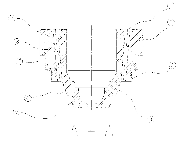
[0023] Put the internal pressure sealing rubber ring 19 on the internal pressure rubber ring sealing column 5, and fit it in clearance. Put the external pressure sealing rubber ring 18 into the groove 14 of the external pressure sealing rubber ring to cooperate with it. The cooling water ring body 12 is screwed to the fixed hot nozzle body 9, and after tightening, the internal pressure sealing rubber ring 19 and the internal pressure rubber ring sealing column 5 are in surface contact to play the role of sealing water. The external pressure sealing rubber ring 18 is in contact with the external pressure sealing rubber ring groove 14 to play the role of sealing water.

[0024] Weld the connection between the fixed hot nozzle body 9 and the cooling water ring body 12 . The first welding point 17 and the second welding point 20 ...


PUM


Abstract

The invention discloses a cooling water ring device for an injection mold, belonging to the technical field of molds. The device mainly comprises a fixed hot nozzle body, a cooling water ring body, an external pressure sealing rubber ring, an internal pressure sealing rubber ring, a common sealing rubber ring and the like, wherein the internal pressure sealing rubber ring is in surface contact with the outer wall and the root of an internal pressure rubber ring sealing column, and is in surface contact and seal fit with the cooling water ring body; the external pressure sealing rubber ring is in surface contact with the inner ring and the bottom of an external pressure sealing rubber ring groove, and is in surface contact and seal fit with the fixed hot nozzle body; the fixed hot nozzle body is in threaded fit with the cooling water ring body and is sealed through welding spots. Natural water flows into a ring-shaped cavity through a water inlet passage hole in order to cool the periphery of the hot nozzle, and then flows out of the cooling water ring device through a water outlet passage hole; the cooling water ring device can rapidly absorb the heat at the periphery of the hot nozzle without local water stagnation, thus solving the undesirable situations of flow mark, gas mark and wire drawing derived from the fact that the surface temperature of the product is difficult to control.

Description

technical field [0001] The invention belongs to the technical field of moulds, and relates to a cooling water ring device for a mould, in particular to an injection mold with a hot runner system. Background technique [0002] At present, for injection molds with a hot runner system, the temperature of the main gate, manifold and hot nozzle is controlled by the hot runner temperature controller, and the template embedded with the main gate, manifold and hot nozzle is controlled by natural water. Cool, and use a mold temperature regulator to control the temperature of the template. [0003] When controlling the temperature of the mold and the hot runner, the most important thing is to effectively control the temperature around the hot nozzle of the hot runner to ensure the quality of the product. Process linear waterway holes in the block. This kind of waterway hole is easy to process, but limited by its processing method, it can only control the temperature on both sides of...

Claims


Application Information

Patent Timeline
Patent Type & Authority Patents(China)
IPC IPC(8): B29C45/73
Inventor 许斌
Owner DALIAN LUANYI PRECISION ENG
Why Eureka
Try Eureka