Heat Exhanger with Varying Cross Sectional Area of Conduits

a technology of cross sectional area and conduit, which is applied in the direction of corrosion prevention, chemical/physical/physicochemical processes, coatings, etc., can solve the problems of oversized heat exchangers and inability to achieve uniform flow conditions, and achieve uniform temperature control, prevent erosion or corrosion, and improve peak heat transfer capacity

Inactive Publication Date: 2009-04-23
ASHE MORRIS LTD
View PDF16 Cites 5 Cited by
  • Summary
  • Abstract
  • Description
  • Claims
  • Application Information

AI Technical Summary

Benefits of technology

[0017]Accordingly the present disclosure provides an improved method of designing and using heat exchangers where the process conduit area is controlled in order to achieve a desired velocity profile within the heat exchanger. The concept is called ‘variable volume’. Variable volume heat exchangers deliver more uniform temperature control throughout the heat exchanger and may also be used to create non uniform temperature control profiles. The technique is also used to achieve better peak heat transfer capacity for exothermic and endothermic processes. Variable volume is also used to achieve preferred velocity profiles within heat exchangers to prevent erosion or corrosion. The technique may also be employed to prevent fragile process materials from being damaged or to entrain or disentrain solids or liquid droplets. The technique may also be used to build heat exchangers which are smaller, cheaper, more efficient and have lower pressure drops.

Problems solved by technology

In some cases, uniform flow conditions cannot be achieved due to the internal geometry of the process conduit.
If account is not taken of these localised variations, the heat exchanger may be oversized (in terms of heat transfer capacity and process conduit area) in some areas and undersized in others.

Method used


Image

  • Heat Exhanger with Varying Cross Sectional Area of Conduits
  • Heat Exhanger with Varying Cross Sectional Area of Conduits
  • Heat Exhanger with Varying Cross Sectional Area of Conduits

Examples


Embodiment Construction

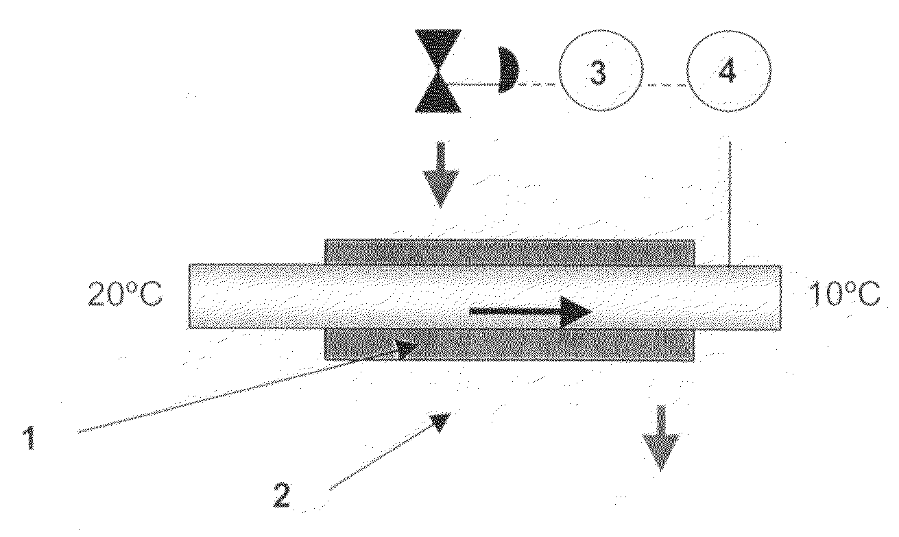
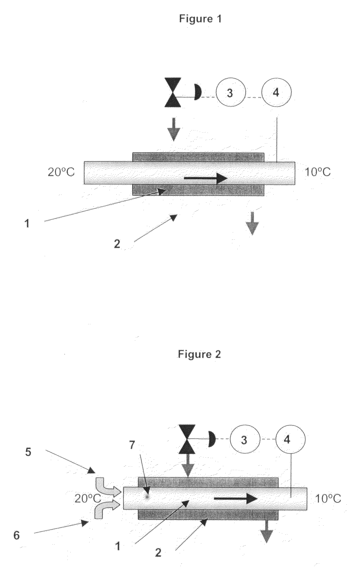
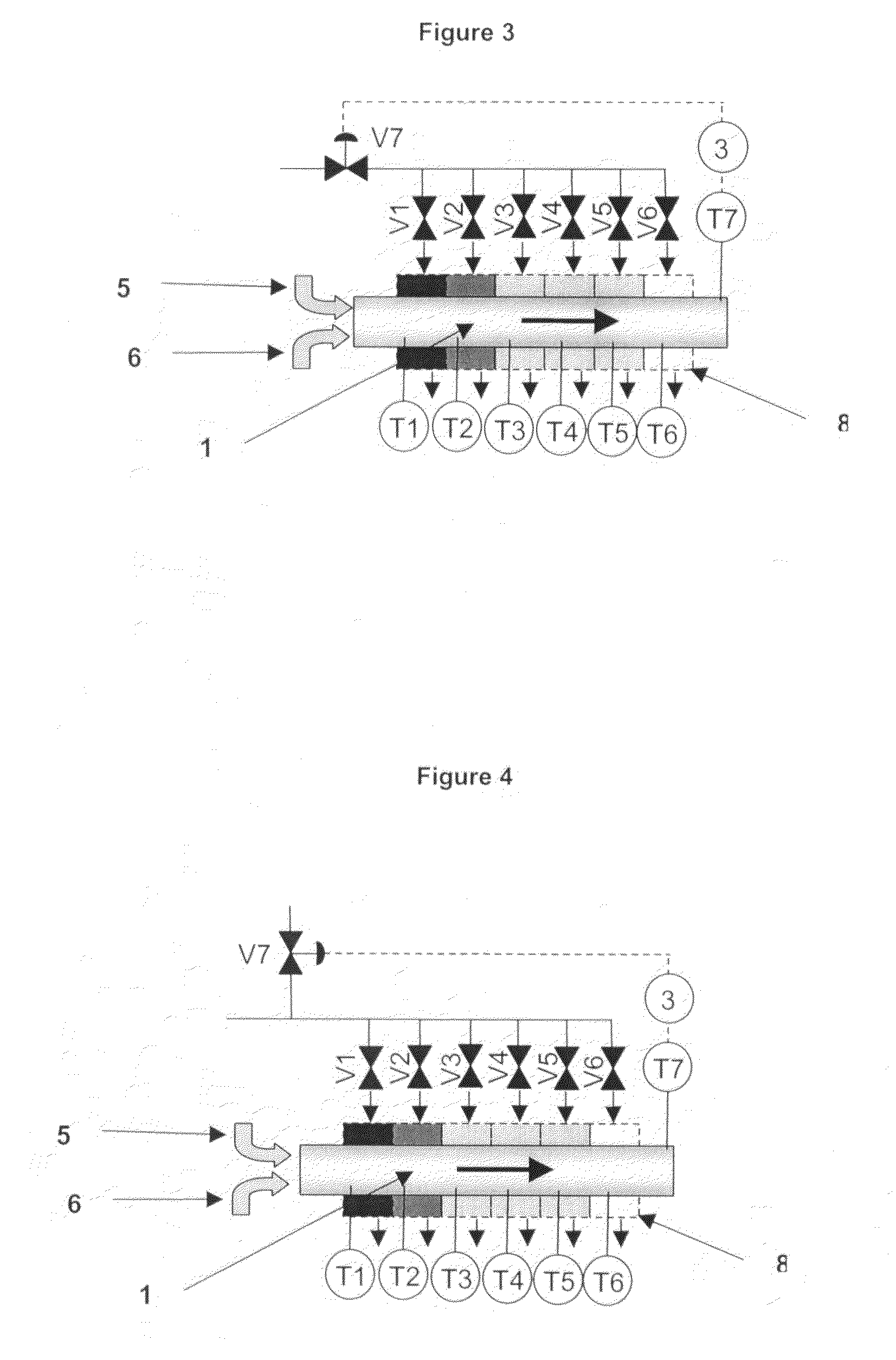
[0040]To illustrate the problem of non uniform heat load within a heat exchanger, FIG. 1 shows a process material (1) flowing through a long pipe around which is a cooling jacket (2). A temperature probe (4) is located in the pipe to measure the temperature of the process material emerging from the cooling pipe. A signal from this temperature probe is taken to a controller (3) and this is used to regulate jacket cooling. This allows the operator to control the final product temperature. FIG. 1 assumes that the process material is being cooled from 20° C. on entry into the pipe down to 10° C. on exit from the pipe. In this case therefore the temperature of the process material within this system is always between 20° C. and 10° C.

[0041]Consider now FIG. 2 where the process material (1) is a reacting mixture of two chemicals (5&6) which is liberating heat. If the heat exchanger is designed as a single stage, the zone where the two chemicals meet will get very hot even though the final...


PUM

PropertyMeasurementUnit
temperatureaaaaaaaaaa
residence timeaaaaaaaaaa

Abstract

A process involving heat exchange that employs heat exchangers where the process material flows over a heat transfer surface in which a process material passes through the process conduit of a heat exchanger wherein the desired velocity profile of the process material passing through the process conduit is achieved by varying the cross sectional area of the process conduit in 3 or more locations along the path length of the process conduit which allows better regulation of heating or cooling within the system which, for some processes, will result in improved temperature control.

Description

BACKGROUND[0001]1. Field of the Disclosure[0002]This present disclosure relates to processes involving heat exchange that employ heat exchangers where the process material flows over a heat transfer surface. Typical examples include plate heat exchangers, shell and tube heat exchangers, drilled block heat exchangers, jacketed tanks, jacketed pipes, vessels with internal coils etc. The disclosure allows better regulation of heating or cooling within the system which, for some processes, will result in improved temperature control. disclosure[0003]2. Discussion of the Background Art[0004]In this document, the material which is required to be heated or cooled within the heat exchanger is referred to as the ‘process material’. The ‘process material’ may be a liquid, an emulsion, a super critical fluid, a vapour, a gas, a paste, solid particulates or a combination of these.[0005]The phrase ‘process conduit’ refers to the space (such as channel, pipe, gap between plates etc) through which...

Claims


Application Information

Patent Timeline
Patent Type & Authority Applications(United States)
IPC IPC(8): F28F13/08B01J19/00
CPCB01J19/0013B01J2219/00085F28F13/08B01J2219/2462F28D2021/0022B01J2219/00873
Inventor ASHE, ROBERT
Owner ASHE MORRIS LTD
Why Eureka
Try Eureka