Emergency traction system applied to urban mass transit

An urban rail transit and traction system technology, applied in the field of emergency traction systems, can solve the problems of safety to be improved, fewer cycles, and high energy conversion efficiency, so as to reduce the probability of passenger backlog and stay, avoid public safety, and speed up rescue. Effect

Inactive Publication Date: 2012-01-04
TONGJI UNIV
View PDF2 Cites 28 Cited by
  • Summary
  • Abstract
  • Description
  • Claims
  • Application Information

AI Technical Summary

Problems solved by technology

However, the charging time is long, the charging and discharging current is small, sensitive to temperature, the number of cycles is small, and the life is short; while the supercapacitor has high power density, low energy density, large charging and discharging current, high energy conversion efficiency, long cycle life, and safety. High coefficient, wide applicable temperature range, green and environmental protection; flywheel also has high power density, long life, friendly to the environment, high energy utilization rate, but expensive, safety needs to be improved
[0003] Under 750V grid voltage, Bombardier has installed supercapacitors on vehicles for braking energy recovery, and also installed batteries separately as a power source for empty vehicles to return to the warehouse. However, there is still no application of hybrid energy storage devices under 1500V grid voltage. At the same time, it is the first time in China to use the on-board energy storage system to implement heavy-duty emergency vehicle transfer

Method used


Image

  • Emergency traction system applied to urban mass transit
  • Emergency traction system applied to urban mass transit
  • Emergency traction system applied to urban mass transit

Examples


Embodiment 1

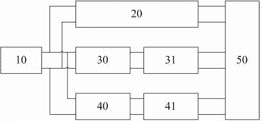
[0025] Embodiment 1: An emergency traction system applied to urban rail transit. It includes a power supply network 10 for providing electric energy, an energy storage element 41 for high-energy or high-power discharge, a power conversion device 40 for controlling energy conversion and charge and discharge management, and a power conversion device 40 for controlling the operation of the train and driving the train. Traction motor 31, auxiliary system 20 for power consumption and energy consumption except for traction power energy demand, and general controller 50 for controlling all the above units.

[0026] The power supply network 10 for providing electric energy, including traction substations, feeder networks, etc., is the place where train traction absorbs power energy and feeds back power energy when the train is running normally, and usually refers to overhead power supply lines. Its output end is respectively connected with the power conversion device 40, the main trac...


PUM


Abstract

The invention relates to an emergency traction system applied to urban mass transit. The system comprises a power supply network, an auxiliary system of an urban mass vehicle, a main traction invertor, a traction motor, a power conversion device, an energy storage component and a master controller; the output end of the power supply network is connected with the power conversion device, the main traction invertor and the auxiliary system of the urban mass vehicle respectively; one end of the energy storage component is connected with the high-voltage side of the power supply network, and one end of the energy storage component is connected with the power supply network; the high-voltage side of the power conversion device is connected with the main traction invertor and the auxiliary system of the urban mass vehicle, and the low-voltage side of the power conversion device is connected with the energy storage component; and the traction motor is connected with the output end of the main traction invertor, and drives a train to run; and the power supply network, the auxiliary system of the urban mass vehicle, the main traction invertor, the traction motor, the power conversion device and the energy storage component are connected with the master controller through a communication bus. The system is suitable for high voltage grades, has a smaller volume and long service life, is high in reliability, and wide in an application range, and can be controlled flexibly, the traction load and distance are larger; and time of return on investment is short.

Description

technical field [0001] The invention relates to an emergency traction system applied to urban rail transit. Background technique [0002] Batteries, supercapacitors and flywheels are three types of energy storage components that are mainly used in urban rail transit. Among them, batteries have high energy density, low power density, more energy that can be stored, and stable discharge current. However, the charging time is long, the charging and discharging current is small, sensitive to temperature, the number of cycles is small, and the life is short; while the supercapacitor has high power density, low energy density, large charging and discharging current, high energy conversion efficiency, long cycle life, and safety. High coefficient, wide applicable temperature range, green and environmental protection; flywheel also has high power density, long life, friendly to the environment, high energy utilization rate, but expensive, and safety needs to be improved. [0003] ...

Claims


Application Information

Patent Timeline
Patent Type & Authority Applications(China)
IPC IPC(8): B60L9/00B60L15/00B60L7/10H02J15/00
CPCY02T90/16Y02T10/7241Y02T10/72
Inventor 袁登科顾帅韦莉李济棋姚勇涛沈小军周巧莲
Owner TONGJI UNIV
Why Eureka
Try Eureka