Method and device for liquefying natural gas by using propylene precooling mixed cryogen
A liquefied natural gas and mixed refrigerant technology, applied in refrigeration and liquefaction, liquefaction, gas fuel and other directions, can solve the problems of clogging pipelines and equipment, affecting the normal operation of the main refrigeration cycle, etc., to achieve convenient operation, high energy consumption utilization, The effect of improving the extraction effect
- Summary
- Abstract
- Description
- Claims
- Application Information
AI Technical Summary
Problems solved by technology
Method used
Image
Examples
Embodiment 1
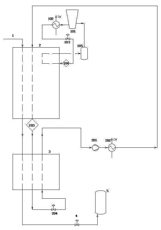
[0033] The device used in this embodiment is as figure 1 As shown, it includes a precooling circulation system, a cryogenic circulation system and a natural gas liquefaction system. The precooling circulation system is composed of a precooling compressor 101, a precooling water cooler 102, an auxiliary cooling box 2, and a first precooling agent throttle valve 103. 1. The first gas-liquid separator 105 forms a closed circulation system through pipelines;
[0034] The cryogenic cycle system is a closed refrigeration cycle system formed by a cryogenic cycle compressor 201, a cryogenic water cooler 202, an auxiliary cold box 2, a main cold box 3, and a cryogenic throttle valve 204 through pipelines;
[0035] Among them, the auxiliary cold box 2, the main cold box 3 and the natural gas throttle valve 4 are connected through natural gas inlet and outlet pipelines to form a natural gas liquefaction system.
[0036] The pre-cooling refrigerant used in the pre-cooling circulation sys...
Embodiment 2
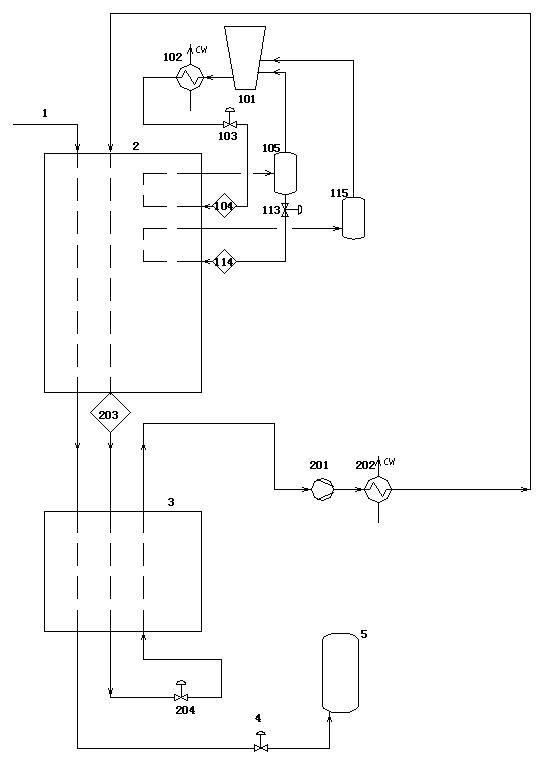
[0044] The device used in this embodiment is as figure 2 As shown, it includes a precooling circulation system, a cryogenic circulation system and a natural gas liquefaction system. The precooling circulation system is composed of a precooling compressor 101, a precooling water cooler 102, an auxiliary cooling box 2, and a first precooling agent throttle valve 103. , the first gas-liquid separator 105, the second precoolant throttle valve 113, and the second gas-liquid separator 115 form a closed circulation system through pipelines;
[0045] The cryogenic cycle system is a closed refrigeration cycle system formed by a cryogenic cycle compressor 201, a cryogenic water cooler 202, an auxiliary cold box 2, a main cold box 3, and a cryogenic throttle valve 204 through pipelines;
[0046] Among them, the auxiliary cold box 2, the main cold box 3 and the natural gas throttle valve 4 are connected through natural gas inlet and outlet pipelines to form a natural gas liquefaction sys...
Embodiment 3
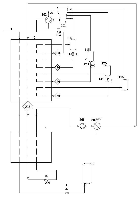
[0056] The device used in this embodiment is as image 3 As shown, it includes a precooling circulation system, a cryogenic circulation system and a natural gas liquefaction system. The precooling circulation system is composed of a precooling compressor 101, a precooling water cooler 102, an auxiliary cooling box 2, and a first precooling agent throttle valve 103. , the first gas-liquid separator 105, the second precoolant throttle valve 113, the second gas-liquid separator 115, the third precoolant throttle valve 123, the third gas-liquid separator 125, the fourth precoolant The throttle valve 133 and the fourth gas-liquid separator 135 form a closed circulation system through pipelines;
[0057] The cryogenic cycle system is a closed refrigeration cycle system formed by a cryogenic cycle compressor 201, a cryogenic water cooler 202, an auxiliary cold box 2, a main cold box 3, and a cryogenic throttle valve 204 through pipelines;
[0058] Among them, the auxiliary cold box ...
PUM
 Abstract
Description
Claims
Application Information
 - R&D
- Intellectual Property
- Life Sciences
- Materials
- Tech Scout
- Unparalleled Data Quality
- Higher Quality Content
- 60% Fewer Hallucinations
Browse by: Latest US Patents, China's latest patents, Technical Efficacy Thesaurus, Application Domain, Technology Topic, Popular Technical Reports.
© 2025 PatSnap. All rights reserved.Legal|Privacy policy|Modern Slavery Act Transparency Statement|Sitemap|About US| Contact US: help@patsnap.com


