
Solar battery with black silicon structure on emitter and preparation method of solar battery

A solar cell and emitter technology, applied in photovoltaic power generation, circuits, electrical components, etc., can solve the problems of low open circuit voltage of black silicon solar cells, uneven doping distribution of pn junctions, etc., to improve short-wave quantum efficiency and reduce surface Recombination rate, effect of reducing surface roughness

Active Publication Date: 2012-01-04
INST OF MICROELECTRONICS CHINESE ACAD OF SCI
View PDF3 Cites 7 Cited by
  • Summary
  • Abstract
  • Description
  • Claims
  • Application Information

AI Technical Summary

Problems solved by technology

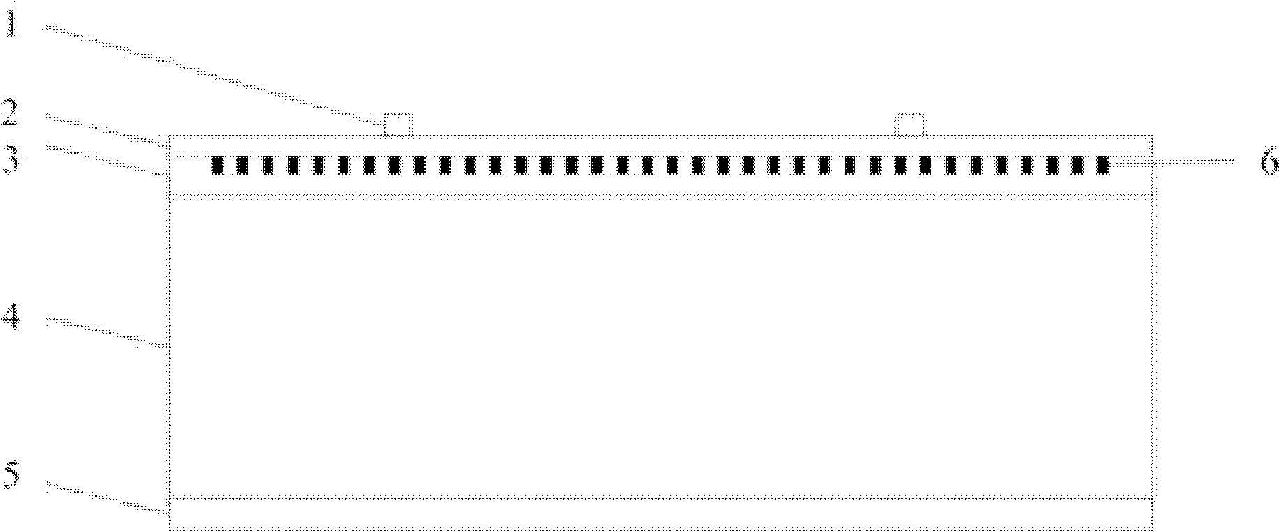
[0004] In order to solve the problems of low open circuit voltage of black silicon solar cells and uneven doping distribution of pn junctions, the present invention provides a solar cell with a black silicon structure on the emitter. The solar cell includes a metal grid electrode, a passivation layer, An emitter, a black silicon layer, a silicon substrate and a metal back electrode; the metal back electrode is located on the back of the silicon substrate, the emitter is located on the silicon substrate, and the black silicon layer is located on the emitter On the pole, the passivation layer is located on the black silicon layer, and the metal gate electrode is located on the passivation layer

Method used


Image

  • Solar battery with black silicon structure on emitter and preparation method of solar battery
  • Solar battery with black silicon structure on emitter and preparation method of solar battery
  • Solar battery with black silicon structure on emitter and preparation method of solar battery

Examples


Embodiment Construction

[0024] In order to deeply understand the present invention, the present invention will be described in detail below in conjunction with the accompanying drawings and specific embodiments.

[0025] see figure 1 , the embodiment of the present invention provides a solar cell with a black silicon structure on the emitter, the solar cell includes a metal grid electrode 1, a passivation layer 2, an emitter 3, a black silicon layer 6, a silicon substrate 4 and a metal back Electrode 5. Wherein, the metal back electrode 5 is located on the back side of the silicon substrate 4, the emitter 3 is located on the silicon substrate 4, the black silicon layer 6 is located on the emitter 3, the passivation layer 2 is located on the black silicon layer 6, and the metal grid electrode 1 on passivation layer 2.

[0026] The silicon substrate 4 can be p-type monocrystalline silicon or polycrystalline silicon, and the doping type of the emitter 3 is n-type; or, the silicon substrate 4 can be n-...


PUM


Abstract

The invention discloses a solar battery with a black silicon structure on an emitter and a preparation method of the solar battery, and belongs to the technical field of manufacturing of solar battery devices. The solar battery comprises a metal grid line electrode, a passivation layer, the emitter, a black silicon layer, a silicon substrate and a metal back electrode, wherein the metal back electrode is positioned on the back surface of the silicon substrate; the emitter is positioned on the silicon substrate; the black silicon layer is positioned on the emitter; the passivation layer is positioned on the black silicon layer; and the metal grid line electrode is positioned on the passivation layer. The preparation method comprises the following steps of: preparing the metal back electrode on the back surface of the silicon substrate; preparing the emitter on the surface of the silicon substrate; preparing the black silicon layer on the emitter; preparing the passivation layer on the black silicon layer; preparing the metal grid line electrode on the passivation layer; and sintering the silicon substrate. By the structure of the solar battery provided by the invention, the uniformity of doping distribution of pn junctions can be effectively improved, and the open circuit voltage of the solar battery is improved, so that the efficiency of the solar battery is improved.

Description

technical field [0001] The invention relates to the technical field of solar cell device manufacturing, in particular to a solar cell with a black silicon structure on an emitter and a preparation method thereof. Background technique [0002] The continuous reduction of non-renewable energy on the earth makes energy prices rise day by day, and the energy competition between countries continues to intensify. It is urgent to develop new renewable energy sources. As a resource-rich, green and environmentally friendly renewable energy, solar energy will play a major role in the supply of new energy in the future. As a device that effectively utilizes solar light energy, solar cells provide an effective solution for the utilization of solar energy. Therefore, high-efficiency and low-cost solar cells will become the direction of solar cell exploration and research. [0003] At present, one way to study high-efficiency solar cells is to prepare a light-trapping structure on the ...

Claims


Application Information

Patent Timeline
Patent Type & Authority Applications(China)
IPC IPC(8): H01L31/0216H01L31/0352H01L31/18
CPCY02E10/50H01L31/02167
Inventor 夏洋刘邦武沈泽南李超波刘杰李勇滔
Owner INST OF MICROELECTRONICS CHINESE ACAD OF SCI
Learn More