Underground self-charging power supply

A self-charging and rechargeable battery technology, applied in battery circuit devices, current collectors, electric vehicles, etc., can solve problems such as unsuitable application of oil and gas production wells

Inactive Publication Date: 2012-01-04
PETROCHINA CO LTD
View PDF6 Cites 3 Cited by
  • Summary
  • Abstract
  • Description
  • Claims
  • Application Information

AI Technical Summary

Problems solved by technology

This patent is mainly used in drilling, using the rotation of the drill pipe to genera

Method used


Image

  • Underground self-charging power supply
  • Underground self-charging power supply
  • Underground self-charging power supply

Examples


Embodiment Construction

[0023] In order to make the object, technical solution and advantages of the present invention clearer, the present invention will be described in further detail below in conjunction with the embodiments and accompanying drawings. Here, the exemplary embodiments and descriptions of the present invention are used to explain the present invention, but not to limit the present invention.

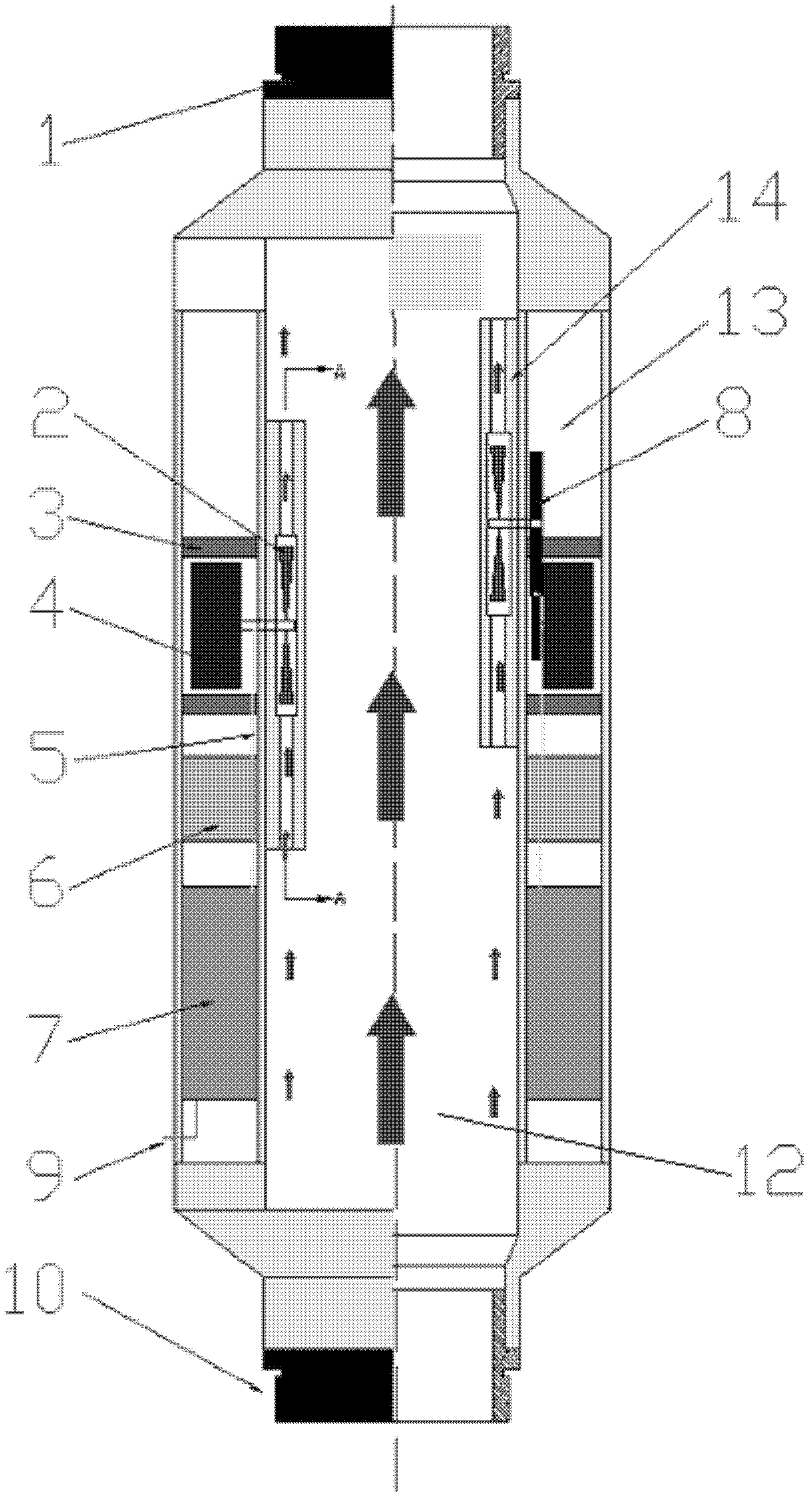
[0024] figure 1 It is a schematic diagram of the structure of the downhole self-charging power supply. As shown in the figure, the downhole self-charging power supply includes: a pipe body, at least one impeller part and at least one charging part.

[0025] The pipe body is a straight pipe, and the pipe body is divided into two parts: the middle fluid channel 12 and the outer cavity 13 located on the periphery of the fluid channel 12 .

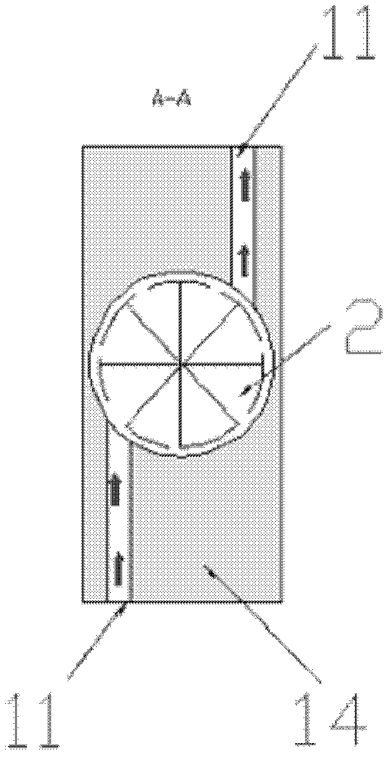
[0026] The impeller portion is disposed on the inner wall of the fluid channel 12 . figure 2 It is a schematic diagram of the A-A section of the impeller. ...


PUM


Abstract

The invention provides an underground self-charging power supply, which comprises a tube body. The tube body is divided into a middle fluid flow passage and an outer cavity positioned on the periphery of the fluid flow passage. An impeller part is arranged on the inner wall of the fluid flow passage, and comprises an impeller protection block, an impeller and two flow passages. An impeller cavity is formed in the impeller protection block and used for arranging the impeller. The two flow passages are communicated with the impeller cavity and used for injecting and discharging a fluid to propel the impeller to rotate. A charging part comprises a generator stator, a generator rotor, a charging circuit and a charging battery. The generator rotor is connected with the impeller by a shaft and rotates along with the impeller. The generator stator is fixedly arranged corresponding to the generator rotor and electrically connected with the charging circuit. The charging circuit is connected with the charging battery. The underground self-charging power supply is used for supplying power to underground intelligent equipment of oil and gas wells.

Description

technical field [0001] The invention relates to the technical field of petroleum exploitation, in particular to an underground self-charging power supply for powering downhole intelligent equipment in oil and gas wells. Background technique [0002] With the increasing modernization and intelligence of oil and gas development and production, downhole intelligent equipment for oil and gas wells has also developed rapidly. Baker Hughes' InCharge intelligent completion system adopts an all-electronic design, using downhole electronically controlled sliding sleeves and an electric downhole wet anchor release system. At present, many research institutions are conducting research on the downhole wireless communication technology of oil and gas wells, relying on this technology to realize the transmission of downhole monitoring data and control signals. The remote control water injection valve used on the water injection well can control the size of the water injection valve throu...

Claims


Application Information

Patent Timeline
IPC IPC(8): H02J7/32F03B13/00F03B3/12
CPCY02E10/223Y02E10/20
Inventor 张卫平沈泽俊钱杰张国文童征
Owner PETROCHINA CO LTD
Why Eureka
Try Eureka