Drive device for a wind turbine

A transmission device and wind turbine technology, applied in the transmission device, mechanical power transmission, wind turbine and other directions, to achieve the effect of reducing the number of parts, low maintenance requirements, and reducing corrosion

Active Publication Date: 2012-01-04
VESTAS WIND SYST AS
View PDF5 Cites 8 Cited by
  • Summary
  • Abstract
  • Description
  • Claims
  • Application Information

AI Technical Summary

Problems solved by technology

There is also a need to make...

Method used


Image

  • Drive device for a wind turbine
  • Drive device for a wind turbine
  • Drive device for a wind turbine

Examples


Embodiment Construction

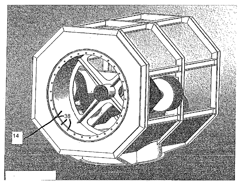
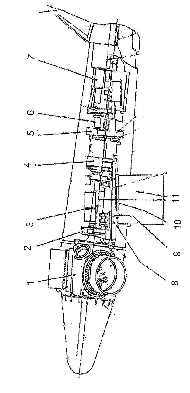
[0029] First, a brief introduction based on figure 1 known cabins. It comprises a rotor hub 1 to which a wind turbine blade (not shown) is attached. Hub 1 is mounted in main bearing 2 and connected to main shaft 3 . The main shaft is connected to main gear 4. The gear 4 is equipped with a brake 5 . The gear is connected to a generator 7 via a connection 6 . The nacelle is also equipped with a swivel bearing 8 , a swivel gear 9 and a swivel ring 10 in order to rotate the nacelle with respect to the tower 11 on which the nacelle is placed.

[0030] The purpose of the invention is to replace the following components in the known nacelle described above: the main shaft 3 , the main gear 4 , the brake 5 and the connection 6 .

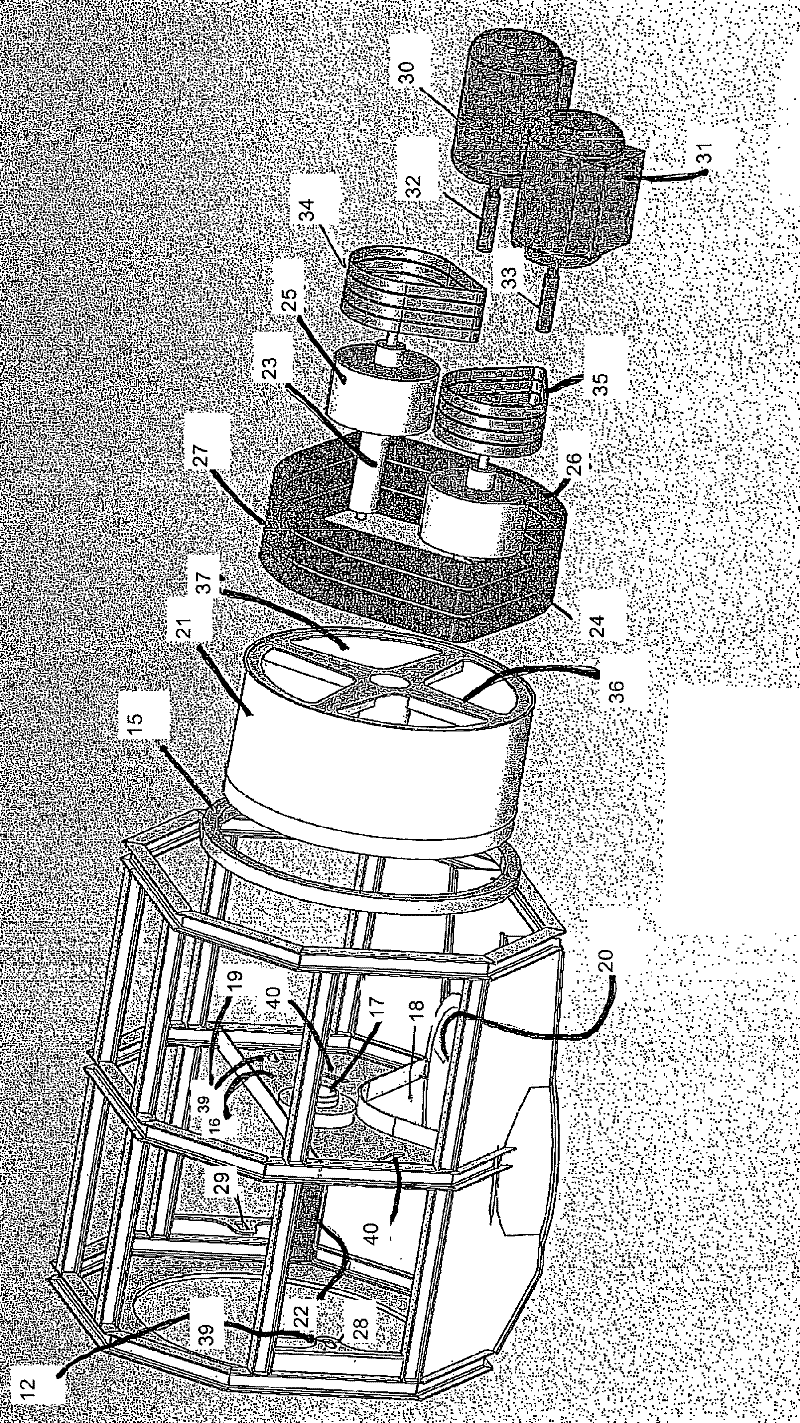
[0031] figure 2 show figure 1 The nacelle in has the transmission according to the invention placed in the desired position and with the known nacelle as background.

[0032] However, in the introduction figure 2 Before, you should refer to Figu...


PUM


Abstract

Drive device for a wind mill comprising a large pulley (21) disposed on a main shaft (22) and at least one belt (27) or chain adapted to transfer rotation from the pulley (21) to a generator (30, 31). The pulley (21) is rotationally coupled to at least two secondary shafts (23, 24), which are disposed parallel to the main shaft (22). One or more belts (27), which transfer the rotation, extend over the pulley (21) and the secondary shafts (23, 24). The secondary shafts (23, 24) are in turn rotationally coupled to at least one, preferably two, electric generators (30, 31).

Description

technical field [0001] The invention relates to a transmission for a wind turbine (wind turbine) according to the preamble of claim 1 attached hereto. Background technique [0002] In most current wind turbines the drive unit is placed in the nacelle which also carries the wind turbine rotor. The nacelle must be arranged on top of a tall mast and rotated so that the rotor is always facing the wind. [0003] This placement of the drive unit results in a significant weight on top of the mast and makes access for maintenance difficult. However it is at this location of the transmission unit and the generator which is widely used as a replacement, that the rotational torque has to be transmitted through the mast via the shaft, which causes losses and requires the mast to be able to absorb the reaction torque from the rotating shaft. Contents of the invention [0004] Therefore, there is an urgent need to simplify and make the transmission unit lighter. There is also a need ...

Claims


Application Information

Patent Timeline
IPC IPC(8): F03D11/02
CPCF05B2260/4021F03D11/02Y02E10/722F16H7/02F03D15/00F03D15/20F03D80/88F03D9/25Y02E10/72F03D1/0658
Inventor G.特詹斯沃尔
Owner VESTAS WIND SYST AS
Why Eureka
Try Eureka