Industrial heat energy recycling system

A thermal energy and industrial technology, applied in the field of thermal energy reuse system, can solve the problems of inability to maintain stable indoor temperature, stable hot spot temperature, unstable outlet pressure fluctuation, large power consumption, etc., to achieve reduced flow, stable outlet pressure, The effect of saving heating energy consumption

Active Publication Date: 2012-01-11
江苏安众环保技术有限公司
View PDF5 Cites 2 Cited by
  • Summary
  • Abstract
  • Description
  • Claims
  • Application Information

AI Technical Summary

Problems solved by technology

[0003] At present, the domestic thermal energy reuse system mainly has the following problems: first, the flow channel or plate surface of the heat exchanger in the heat exchange unit is obviously fouled and sticky, and some of the flow channels are blocked; second, the circulation The water supply adopts a multi-circulation pump system, one for one use and one for standby. The pump motor is directly driven. When switching between start and stop or when the heating load and resistance change suddenly, the pump runs with loud noise, consumes a lot of power, and the outlet pressure fluctuates unstable. ;Third, the temperature control of the heat exchange unit is often realized by adjusting the flow of the heat medium through the temperature signal of the heat supply outlet. Due to the change of the return water temperature and the change of the ambient temperature, the heating effect is poor, and the indoor temperature cannot be kept stable or hot spots can be used. The temperature is stable

Method used


Image

  • Industrial heat energy recycling system
  • Industrial heat energy recycling system

Examples


Embodiment Construction

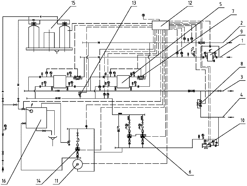
[0013] The present invention will be further described below in conjunction with accompanying drawing.

[0014] As shown in the figure, an industrial heat energy reuse system, the heat energy generated in the industrial production process uses water as a carrier to enter the hot side water inlet pipeline 1, and then the circulating water enters the hot side return water pipeline through the filter 9 with automatic backwash function 2 to form an inner loop. Before entering the return water pipeline 2 on the hot side, the hot water will undergo heat exchange through the heat exchanger 5 and transfer the heat energy to another water circulation system that provides heat energy for customers. A temperature regulating valve 7 is installed in front of the heat exchanger 5 to adjust the heat energy of the customer. The flow of hot water in the hot side water inlet pipeline 1 is adjusted according to the demand condition, and the temperature regulating valve 7 is controlled by the con...


PUM


Abstract

The invention discloses an industrial heat energy recycling system, which comprises a heat side water inlet pipe, a heat side water return pipe, a water supply pipe and a water return pipe, wherein the heat side water inlet pipe and the heat side water return pipe input industrial heat energy; the water supply pipe and the water return pipe recycle the industrial heat energy; the heat side water inlet pipe and the heat side water return pipe as well as the water supply pipe and the water return pipe respectively form two water circulation systems; the water circulation system formed by the water supply pipe and the water return pipe is a closed circulation system; and heat energy between the two water circulation systems is exchanged by a heat exchanger so as to recycle the industrial heat energy. The industrial heat energy recycling system has the beneficial effects that heat exchange effect is obviously improved, outlet pressure is more stable, scale formation and particulate matterblockage can be effectively prevented, a multipoint control strategy of small flow / big temperature difference is adopted to reduce flow, lower electrical load and save operation cost, the industrialheat energy recycling system has the characteristics of artificial intelligence and full automatic control, remote control is realized by a communication interface, heat supply energy consumption is saved, and the operation cost is lowered.

Description

technical field [0001] The invention relates to a thermal energy reutilization system, in particular to a system for reusing thermal energy generated by cooling a power plant or a chemical plant through a heat exchange device. Background technique [0002] With the gradual depletion of non-renewable resources, energy conservation is an urgent topic and eternal pursuit of economic and social development. At present, all countries in the world attach great importance to energy conservation and energy reuse, and invest a lot of manpower and financial resources in research and development of new technologies to improve energy utilization. In recent years, with the development of my country's industry, the demand for energy has also doubled. With the improvement of people's living standards, people have put forward higher requirements for energy. Now industrial production and people's life have produced a relatively large demand for energy. Therefore, the government often takes m...

Claims


Application Information

Patent Timeline
Patent Type & Authority Applications(China)
IPC IPC(8): F24D3/02F24D3/08F24D3/10F24D19/10
Inventor 何文秀朱恩平
Owner 江苏安众环保技术有限公司
Why Eureka
Try Eureka