Condenser with liquid separation type spiral tube structure

A helical tube and condenser technology, applied in the field of heat exchange and heat transfer, can solve the problem of unreported research on the strengthening of condensation phase change heat transfer in the helical tube, and achieve the goal of enhancing heat transfer performance, improving heat transfer efficiency, and improving efficiency Effect

Active Publication Date: 2012-01-11
NORTH CHINA ELECTRIC POWER UNIV (BAODING)
View PDF6 Cites 13 Cited by
  • Summary
  • Abstract
  • Description
  • Claims
  • Application Information

AI Technical Summary

Problems solved by technology

[0005] At present, the research on enhanced condensation heat transfer at home and abroad mainly focuses on the research on smooth straight tubes or straight tubes with inner fins, inner spirals, and inner grooves, but the enhancement of condensation phase change heat transfer in spiral tubes has not been reported yet.

Method used


Image

  • Condenser with liquid separation type spiral tube structure
  • Condenser with liquid separation type spiral tube structure
  • Condenser with liquid separation type spiral tube structure

Examples


Embodiment 1

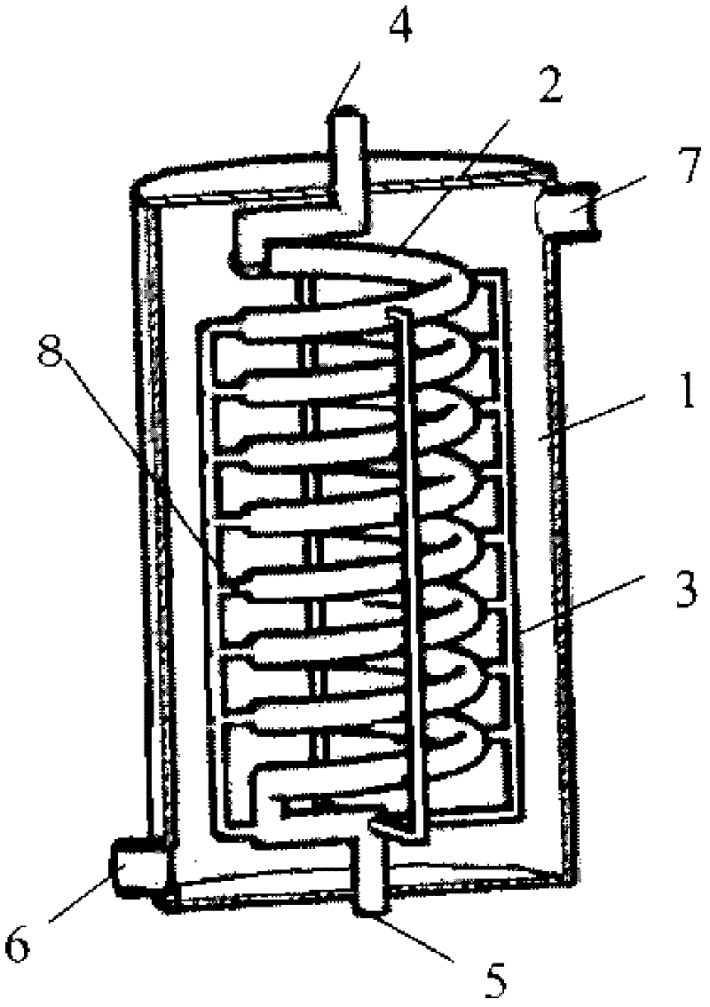
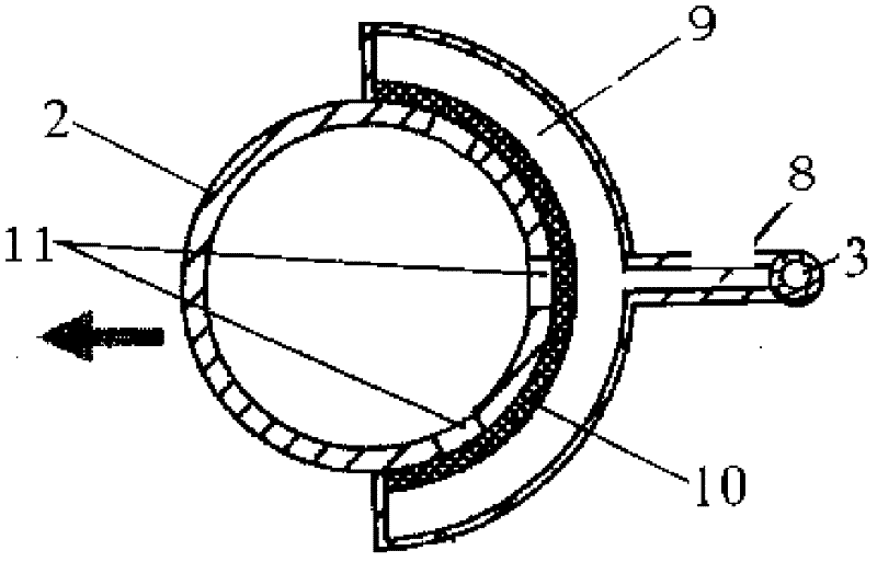
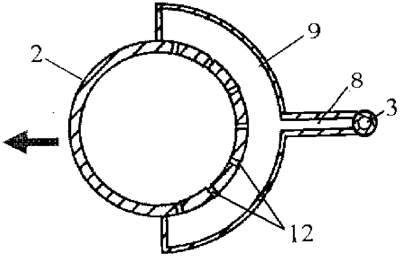
[0029] For the heat exchange process of condensed water, a 2600mm long φ10mm×1mm ordinary smooth copper tube is selected to be wound into a spiral ascending tube with a diameter of 80mm and a pitch of 15mm; a 220mm long φ180mm×5mm stainless steel tube is used as the shell; The first and last ends of the tube are welded to the condensate inlet and outlet tubes with the same diameter as the spiral copper tube, and the inlet and outlet tubes are parallel to the axis of the shell. On the outer circumference side of the spiral tube, micro-holes with a diameter of 1mm are processed on each circle of the spiral tube from four directions, and a smooth copper tube of φ3mm×1mm is welded to it perpendicular to the axis of the shell, and the outer circumference of the spiral tube is The microtubes welded in each direction of the wall are communicated with a copper tube parallel to the axis of the shell φ4mm×1mm, and extend to the end of the spiral tube to connect with the condensate outlet...


PUM


Abstract

The invention discloses a condenser with a liquid separation type spiral tube structure, which belongs to the technical fields of heat exchange and heat transfer. A spiral heat exchange tube is fixed in a shell of the condenser with the liquid separation type spiral tube structure; a liquid guiding tube is distributed on the outer circumference of the spiral heat exchange tube; the upper end of the spiral heat exchange tube is a condensing working substance inlet tube; the lower end of the spiral heat exchange tube is a condensing working substance outlet tube; the upper end of the outer circumference of the shell is a cooling water outlet; and the lower end of the outer circumference of the shell is a cooling water inlet. In a condensing process, a thick liquid film distributed on the side wall surface of the spiral outer circumference is derived in a non-dynamical way by utilizing the combined action of surface tension, capillary force and centrifugal force; a thin liquid film is promoted to transfer heat in a condensation phase change process; and the heat resistance of a condensed liquid film on the side of the outer circumference of a spiral tube is decreased, thereby obviously improving the heat exchange performance on the side of a condensation phase change tube. By using the condenser with the liquid separation type efficient spiral tube, a condensate liquid is separated mainly by means of the centrifugal force and the capillary force without being influenced by gravity, and the condensation heat exchange coefficient can be obviously improved both in a ground environment or a microgravity environment.

Description

technical field [0001] The invention belongs to the technical field of heat exchange and heat transfer, in particular to a condenser with a liquid separation spiral tube structure. Background technique [0002] A large amount of low-grade waste heat (such as flue gas waste heat, steam waste heat, etc.) released in industrial processes needs to be utilized, and its heat mainly includes sensible heat and latent heat. Taking the flue gas of a coal-fired boiler as an example, the volume share of water vapor is about 8%, and the latent heat carried accounts for about 30% of the total waste heat. It accounts for about 65% of the total waste heat; it can be seen that the use of condensation heat exchange technology to recover latent heat in waste heat can greatly improve the utilization rate of heat energy recovery. [0003] At the same time, compared with the general straight tube shell-and-tube heat exchanger, the spiral tube heat exchanger has the advantages of large heat trans...

Claims


Application Information

Patent Timeline
Patent Type & Authority Applications(China)
IPC IPC(8): F25B39/04F28F1/12
Inventor 陈宏霞徐进良张伟
Owner NORTH CHINA ELECTRIC POWER UNIV (BAODING)
Why Eureka
Try Eureka