Method for barrier perception based on airborne binocular vision

A binocular vision and obstacle technology, applied in the field of aircraft navigation and computer vision, can solve the problems of inability to apply the aircraft task execution stage, unable to meet the needs of navigation applications, unable to meet real-time navigation, etc. The effect of good real-time performance and simple generation method

Active Publication Date: 2012-01-11
SHENZHEN AUTEL INTELLIGENT AVIATION TECH CO LTD
View PDF2 Cites 79 Cited by
  • Summary
  • Abstract
  • Description
  • Claims
  • Application Information

AI Technical Summary

Problems solved by technology

[0004] The problem with existing vision-based obstacle perception methods is that the application of computer vision methods in aircraft mainly focuses on autonomous landing, scene matching and target recognition, and visual-inertial integrated navigation.
The vision method in autonomous landing focuses on the landing phase of the aircraft, and requires known landing field information, which cannot be applied to the mission execution phase of the aircraft; for scene matching and target recognition, it is necessary to establish an on-board database for scene matching to find known target information and Using visual methods to obtain the relative position of the target, but the natural environment in which the aircraft is flying is powerless; while the navigation method that combines computer vision technology with airborne inertial navigation data has a large amount of calculation, when the flight environment is complex Unable to meet the requirements of real-time navigation
Therefore, although there are researches on the application of vision methods to aircraft navigation, on the one hand, these methods require known target information or manual setting of reference information, and on the other hand, there are potential real-time defects, which cannot meet the needs of the natural environment in which the aircraft performs tasks. Navigation application requirements in

Method used


Image

  • Method for barrier perception based on airborne binocular vision
  • Method for barrier perception based on airborne binocular vision
  • Method for barrier perception based on airborne binocular vision

Examples


Embodiment Construction

[0015] Embodiments of the present invention are described in detail below, examples of which are shown in the drawings, wherein the same or similar reference numerals designate the same or similar elements or elements having the same or similar functions throughout. The embodiments described below by referring to the figures are exemplary only for explaining the present invention and should not be construed as limiting the present invention.

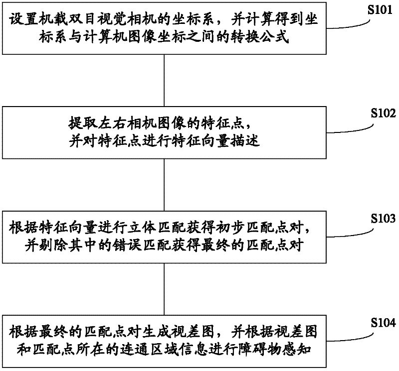
[0016] Such as figure 1 As shown, the obstacle perception method based on airborne binocular vision according to an embodiment of the present invention includes the following steps:

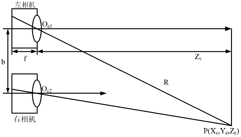
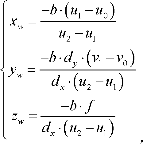
[0017] Step S101, setting the coordinate system of the onboard binocular vision camera, and calculating a conversion formula between the computer image coordinates of the image formed by the onboard binocular vision camera and the coordinate system according to the coordinate system.

[0018] The establishment of the image coordinate system and the measure...


PUM


Abstract

The invention provides a method for barrier perception based on airborne binocular vision. The method comprises the following steps of setting a coordinate system of an airborne binocular vision camera, calculating a formula for conversion between the coordinate system and computer image coordinates of an image obtained by the airborne binocular vision camera according to the coordinate system, wherein the airborne binocular vision camera comprises a left camera and a right camera, extracting characteristic points of an image obtained by the airborne binocular vision camera, carrying out a characteristic vector description process on the characteristic points, carrying out stereo matching of left and right images according to characteristic vectors of the characteristic points to obtain preliminary matching point pairs, eliminating error matching in the preliminary matching point pairs to obtain final matching point pairs, creating a disparity map according to the final matching point pairs, and carrying out barrier perception according to the disparity map. The method for barrier perception based on airborne binocular vision has the advantages of strong adaptability, good instantaneity and good concealment performance.

Description

technical field [0001] The invention relates to the technical fields of aircraft navigation and computer vision, in particular to an obstacle perception method based on airborne binocular vision. Background technique [0002] With the continuous development of aircraft-related technologies and the complexity of its application scenarios, higher requirements are put forward for its environmental perception capabilities. Vision-based navigation technology has the advantages of wide detection range and large information capacity, especially in the approach flight environment, which has the characteristics of rapid capture of environmental changes and sharp response, and has been increasingly used in aircraft guidance / navigation research focus on. [0003] Obstacle perception applications in vision-based flight environments can use monocular or binocular vision, and binocular vision is widely used. Monocular vision uses an onboard camera to acquire flight images, but loses the...

Claims


Application Information

Patent Timeline
Patent Type & Authority Applications(China)
IPC IPC(8): G01C11/00G01C11/04
Inventor 戴琼海李一鹏
Owner SHENZHEN AUTEL INTELLIGENT AVIATION TECH CO LTD
Why Eureka
Try Eureka