Optical head and optical disc apparatus
A technology of optical disc device and optical head, which is applied in the direction of beam guiding device, optical recording head, head configuration/installation, etc., which can solve the problems of unstable amplitude fluctuation and achieve high signal amplification effect
- Summary
- Abstract
- Description
- Claims
- Application Information
AI Technical Summary
Problems solved by technology
Method used
Image

Examples
Embodiment 1
[0058] Use the following figure 1 Embodiments of the present invention will be described.
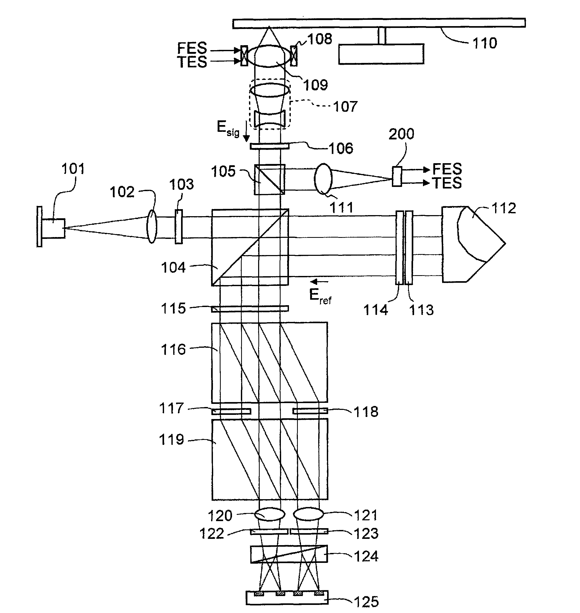
[0059] figure 1 This is the basic embodiment of the optical head of the present invention. The light from the semiconductor laser 101 is converted into parallel light by the collimator lens 102 , passes through the λ / 2 plate 103 , and enters the polarization beam splitter 104 . The polarization beam splitter 104 has a function of transmitting almost 100% of p-polarized light (hereinafter referred to as horizontally polarized light) incident on the splitting surface and reflecting substantially 100% of s-polarized light (hereinafter referred to as vertically polarized light). In this case, by adjusting the rotation angle of the rotation of the optical axis of the λ / 2 plate, the intensity ratio of transmitted light and reflected light can be adjusted. The reflected light (hereinafter referred to as signal light) enters the special polarization beam splitter 105 first. The special pola...
Embodiment 2
[0103] This embodiment is another embodiment in which signal light and reference light are separated again after being combined. Figure 10A structural diagram showing this embodiment. In this case, the signal light is reflected by the optical disc 110 and passes through the polarizing beam splitter 104 following the opposite optical path as in the first embodiment. On the other hand, the reference light passes through the λ / 4 plate (axial direction: 45 degrees relative to the horizontally polarized light), is condensed on the mirror 1003 through the lens 1002 and is reflected to follow the opposite optical path, and reciprocates through the λ / 4 plate 1001, As a result, the polarized light is rotated by 90 degrees and reflected by the polarization beam splitter 104 , at which point the signal light and the reference light are combined in a perpendicular state. The multiplexed light beams are brought into a condensed state by the lens 1004 and then separated in parallel by the...
Embodiment 3
[0107] The present embodiment is another embodiment in which branching is performed to interfere signal light and reference light with mutually different phases, and the process of combining the branched signal light and reference light is performed simultaneously. Figure 12 A structural diagram showing this embodiment. This embodiment is the same as the first embodiment until the signal light and the reference light pass through the λ / 2 plate (axial direction: 22.5 degrees relative to the horizontally polarized light) 115 . The signal light and reference light are combined by the polarization beam splitter 1201, and two combined beams are emitted. At this time, the polarization states of the signal light and the reference light are as follows: Figure 13 As shown, the horizontally polarized component of the signal light passes through the polarization beam splitter 1201 and is multiplexed with the vertically polarized component of the reference light. Likewise, the vertica...
PUM
 Abstract
Description
Claims
Application Information
 - R&D
- Intellectual Property
- Life Sciences
- Materials
- Tech Scout
- Unparalleled Data Quality
- Higher Quality Content
- 60% Fewer Hallucinations
Browse by: Latest US Patents, China's latest patents, Technical Efficacy Thesaurus, Application Domain, Technology Topic, Popular Technical Reports.
© 2025 PatSnap. All rights reserved.Legal|Privacy policy|Modern Slavery Act Transparency Statement|Sitemap|About US| Contact US: help@patsnap.com