Single-circuit output flyback converter controlled in current mode

A flyback converter, current-mode technology, applied in the output power conversion device, the conversion of DC power input to DC power output, and the adjustment of electrical variables, etc., can solve the problem of low switching frequency, poor anti-interference performance, and filter capacitors. The problems of large volume and weight can achieve the effect of reducing surge overvoltage, good rectification effect, and reducing turn-off loss.

Inactive Publication Date: 2012-01-11
BEIJING STATE GRID PURUI EXTRA HIGH VOLTAGE POWER TRANSMISSION TECH CO LTD
View PDF3 Cites 40 Cited by
  • Summary
  • Abstract
  • Description
  • Claims
  • Application Information

AI Technical Summary

Problems solved by technology

However, the use of a linear power supply requires a huge and heavy transformer, and the volume and weight of the filter capacitor required are also quite large, and the voltage feedback circuit works in a linear state, and there is a certain voltage drop on the regulator tube. When outputting a large operating current It will cause the power consumption of the adjustment tube to be too large, the conversion efficiency is low, and a large heat sink must be installed
The switching power supply has the advantages of small size, light weight, simple circuit structure, wide output voltage range, and modularization, but the traditional switching ...

Method used


Image

  • Single-circuit output flyback converter controlled in current mode
  • Single-circuit output flyback converter controlled in current mode
  • Single-circuit output flyback converter controlled in current mode

Examples


Embodiment Construction

[0019] The present invention will be described in detail below in conjunction with the accompanying drawings and embodiments.

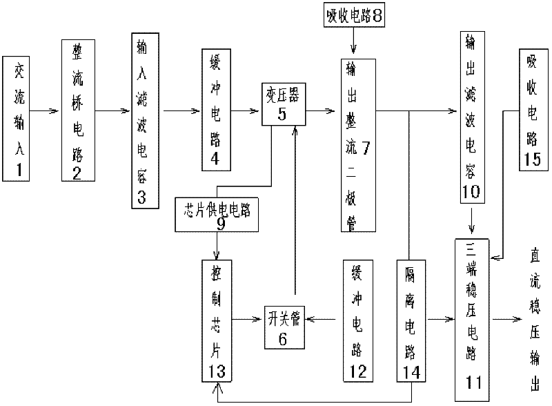
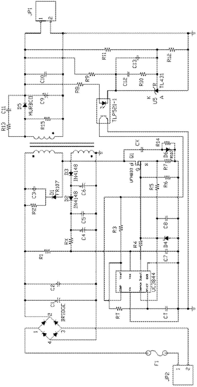
[0020] Such as figure 1 , figure 2 As shown, the present invention includes an AC input source 1, a rectifier bridge circuit 2, an input filter capacitor 3, a first buffer circuit 4, a transformer 5, a switch tube 6, an output rectifier diode 7, a first absorbing circuit 8, and a chip power supply circuit 9. An output filter capacitor 10 , a three-terminal voltage stabilizing circuit 11 , a second buffer circuit 12 , a control chip 13 , an isolation circuit 14 and a second absorbing circuit 15 .

[0021] After the AC input source 1 converts the AC power into unidirectional DC power through the rectifier bridge circuit 2 , the harmonics in the DC power are filtered through the input filter capacitor 3 and then input to the first buffer circuit 4 . The first buffer circuit 4 is connected in parallel to the primary winding of the transformer 5, and th...


PUM


Abstract

The invention relates to a single-circuit output flyback converter controlled in a current mode. The single-circuit output flyback converter comprises an alternating current input source, wherein the alternating current input source inputs direct current to a first buffer circuit through an input filter capacitor after passing through a rectifier bridge circuit; the first buffer circuit is connected in parallel to a primary winding of a transformer, the primary winding is connected with the drain electrode of a switching tube, and a secondary winding is respectively connected with an output rectifier diode and the input end of a first absorption circuit and is connected to a control chip through a chip power supply circuit; the output end of the output rectifier diode is connected to a three-terminal voltage-stabilizing circuit through an output filter capacitor after being connected in parallel with the output end of the first absorption circuit; a second buffer circuit is connected in parallel between the source electrode and the drain electrode of the switching tube, and the grid electrode and the source electrode are respectively connected with the control chip through a sampling resistor; the compensation end of the control chip is connected with the output end of an isolating circuit, the input end of the insolating circuit is connected in parallel with the output filter capacitor, and the other input end of the isolating circuit is connected with the three-terminal voltage-stabilizing circuit which outputs voltage-stabilizing direct current; and a second absorption circuit is arranged in the three-terminal voltage-stabilizing circuit.

Description

technical field [0001] The invention relates to a flyback converter, in particular to a single output flyback converter used for current mode control in the field of switching power supplies. Background technique [0002] At present, in the fields of DC motor speed regulation, battery charging, switching power supply, etc., especially in electric traction, electric vehicles such as subways, urban light rails, electric locomotives, trolleybuses, battery cars, and electric forklifts used to use rheostats to realize electric power. The starting, speed regulation and braking of the car have problems such as high power consumption, low efficiency, stepped speed regulation, and poor running stability. After the introduction of DC chopper, electric vehicles are powered by constant DC power supply (such as battery, uncontrolled rectifier power supply), which can conveniently realize stepless speed regulation and stable operation, and more importantly, save electricity by 20% compare...

Claims


Application Information

Patent Timeline
IPC IPC(8): H02M7/12H02M3/335H02M1/12H02M1/14
Inventor 柏德胜张彪杨佐峰
Owner BEIJING STATE GRID PURUI EXTRA HIGH VOLTAGE POWER TRANSMISSION TECH CO LTD
Why Eureka
Try Eureka