Material-in-air conveying theory principle and technical scheme of conveying material by fluid

A technology of fluid conveying and technical solutions, applied in the field of fluid jet conveying materials, can solve the problems of weakening conveying capacity, affecting the service life of pipeline equipment, and failing to reach the design index of the pneumatic continuous conveying project. Small, the effect of reducing the probability of pipe blockage

Inactive Publication Date: 2012-01-18
何智
View PDF4 Cites 11 Cited by
  • Summary
  • Abstract
  • Description
  • Claims
  • Application Information

AI Technical Summary

Problems solved by technology

[0009] Disadvantages of the existing technology: All equipment that uses air kinetic energy to continuously transport materials basically use nozzles, but all the nozzles of pneumatic conveying pumps have been applied for some patents in spite of various forms, but without exception, they are all Arranged in the middle of the material to be conveyed, the power air is ejected in the middle, and the powder and granular material to be conveyed is outside the air, so that the moving powder and granular material directly contact and rub against the inner wall of the equipment and pipe

Method used


Image

  • Material-in-air conveying theory principle and technical scheme of conveying material by fluid
  • Material-in-air conveying theory principle and technical scheme of conveying material by fluid
  • Material-in-air conveying theory principle and technical scheme of conveying material by fluid

Examples


Embodiment Construction

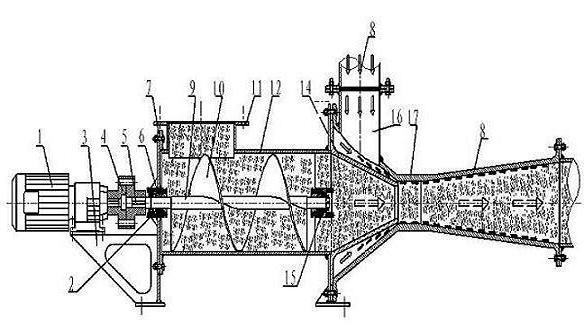
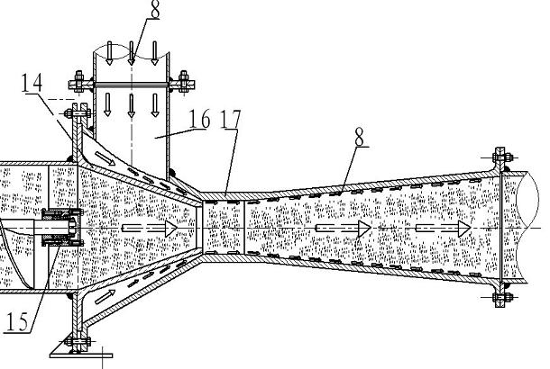
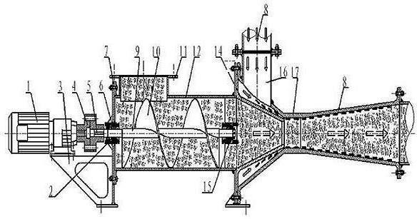
[0030] According to attached figure 1 , 2 As shown, start the power unit (1) and feed gas into the air inlet ⒃ at the same time, and add materials from the feed inlet ⑾. When the power part ⑴ starts, the output shaft of the power part is rigidly connected with the coupling ⑷, and the coupling ⑷ is rigidly connected with the screw pump shaft ⑼ through the key ⑸, thereby driving the rotation of the screw pump shaft ⑼, in which the screw pump shaft ⑼ is supported by the left end bearing Frame ⑼, the right end bearing support frame ⒂ cooperate; the screw pump shaft ⑼ is rigidly connected with the screw blade ⑽, so that the screw pump shaft ⑼ and the screw blade ⑽ rotate together. When the screw blade ⑽ rotates, it provides the speed of the axial movement of the material, and converts the circular motion of the screw blade ⑽ into the axial motion of the material. The screw blade ⑽ is respectively connected to the left end bearing support frame ⑵ and the right end bearing support f...


PUM


Abstract

The invention relates to the field of conveying materials by jetting fluid, in particular to a material-in-air conveying principle and technical scheme of conveying a material by fluid. The device comprises a power part, a base, a material conveying system and a material air-wrapped feeding system. A spiral blade (10) is driven by the power part (1), the spiral blade (10) provides power for the axial movement of materials when rotating, and the circumference movement of the spiral blade (10) is converted to the axial movement of the materials. High pressure air (8) enters an air pipe cavity from a side air inlet, and is annularly jet into a venturi pipe from a gas between the outer side of a nozzle and the venturi pipe. Due to the obvious action of Condar effect, the high pressure air (8) jet from the gap flows forward closely to the inner wall of the venturi pipe, one layer of continuous air film is attached to the inner side of the venturi pipe, and middle materials are wrapped by the air and conveyed forward. The invention has the advantages of good wear resistance property, small conveying resistance, large material to gas ratio, high efficiency, low price, small pump height, adaptability to the conveying of high-temperature materials, coarse powder particles and the like.

Description

technical field [0001] The invention relates to the field of fluid jet conveying materials, in particular to the theoretical principle and technical scheme of the wind-packed material for fluid conveying materials. Background technique [0002] The existing methods of transporting materials by fluid injection are introduced in the appendix "Theoretical and Experimental Research on Gas-Solid Injector" and "Parameter Calculation of a Coal Powder Pneumatic Conveying Injector". Humans have used air force to transport materials since ancient times. , such as blowing air to launch a dart. The use of equipment to transport materials by wind power has a history of about a hundred years. For example, the US Postal Service used wind power and pipelines to distribute letters at the beginning of the last century. However, the large-scale use of pneumatic power to transport powder materials through pipelines in my country did not really begin until the 1980s. [0003] In the past, the ...

Claims


Application Information

Patent Timeline
IPC IPC(8): B65G53/16B65G53/40
Inventor 何智
Owner 何智
Why Eureka
Try Eureka