Optical measurement method and optical measurement device for five-degree-of-freedom rotation errors of spindle

A technology of rotation error and optical measurement, applied in measurement devices, optical devices, instruments, etc., can solve the problems of complex calculation model, complex structure, nonlinearity, etc., and achieve high CCD resolution, low implementation cost, and good stability. Effect

Inactive Publication Date: 2012-01-18
ZHEJIANG UNIV
View PDF4 Cites 22 Cited by
  • Summary
  • Abstract
  • Description
  • Claims
  • Application Information

AI Technical Summary

Problems solved by technology

Korean scholar Hyeong-Joon Ahn proposed a cylindrical capacitive displacement sensor to measure radial displacement (two degrees of freedom). At the same time, the scholar also carried out research on the method of measuring the geometric error of the five degrees of freedom of the rotation axis based on a disc-shaped planar capacitive sensor. Although the method can measure the errors of the five degrees of freedom of the main shaft at the same time, the capacitive sensors are distributed on concentric planes, the calculation model is complex, and there are serious nonlinearities.
Suzhou Guangdong Precision Instrument Co., Ltd. installs a standard ball on the spindle an

Method used


Image

  • Optical measurement method and optical measurement device for five-degree-of-freedom rotation errors of spindle
  • Optical measurement method and optical measurement device for five-degree-of-freedom rotation errors of spindle
  • Optical measurement method and optical measurement device for five-degree-of-freedom rotation errors of spindle

Examples


Embodiment Construction

[0024] The present invention will be further described below in conjunction with the accompanying drawings.

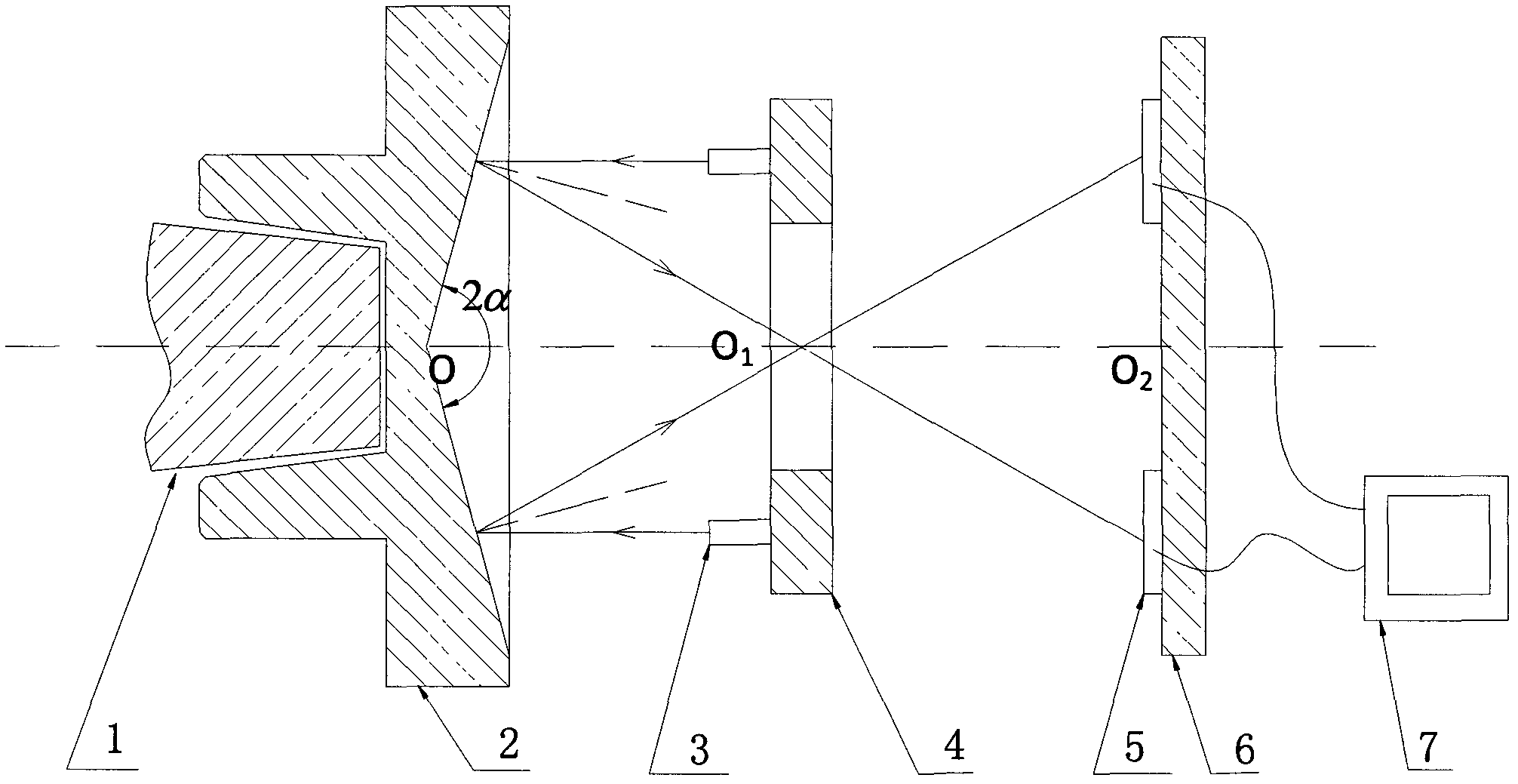
[0025] Such as figure 1 As shown, the present invention installs the flange 2 at the axial end of the main shaft 1 under test, and outside the concave conical reflective surface outside the flange 2, there are four laser generators 3 and four CCDs 5 in sequence and are installed on the respective supports. Arranged alternately, four CCDs 5, the measured spindle 1, flange 2, laser generator support 4 and CCD support 6 are coaxially arranged, and the laser generator support 4 and CCD support 6 can measure the distance in the axial direction. For fine tuning, four CCDs 5 are connected with computer 7 respectively.

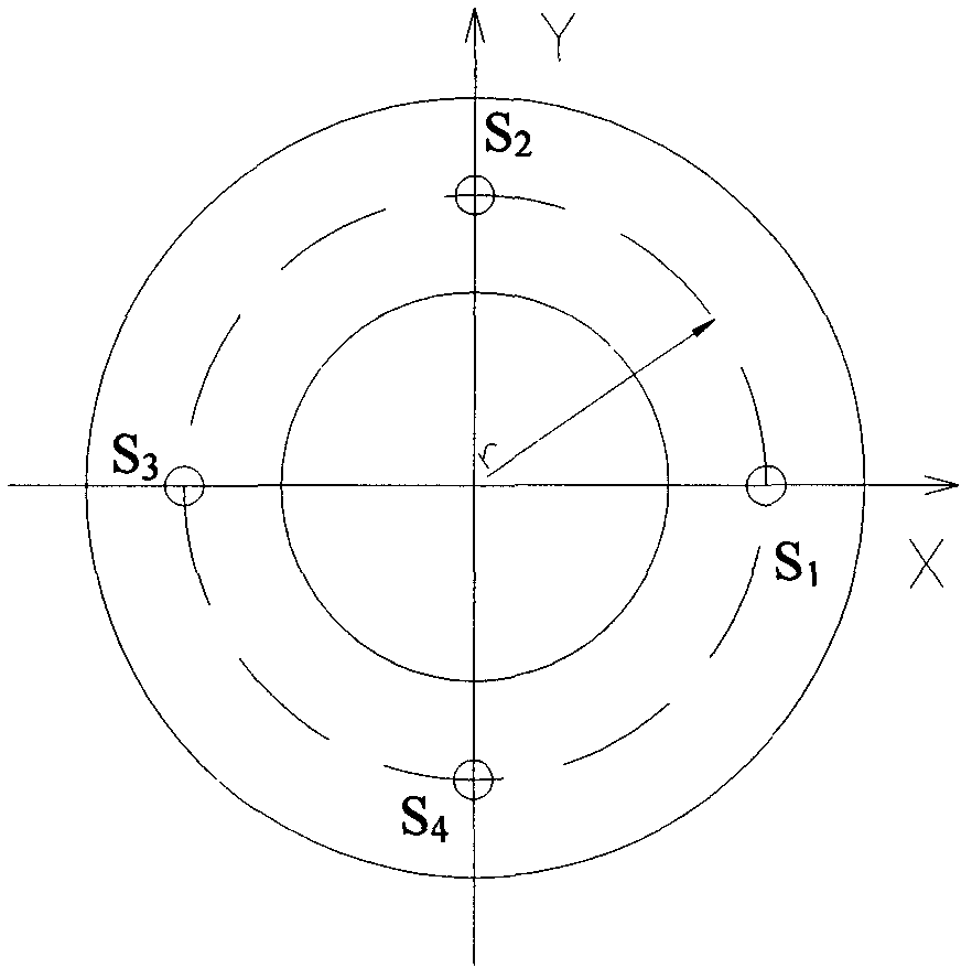
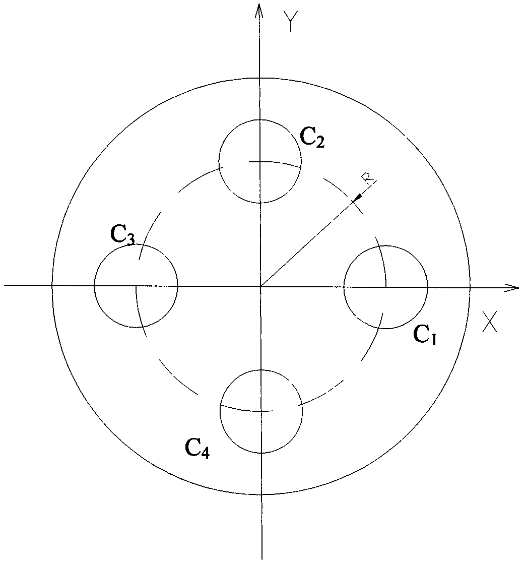
[0026] Among the four laser generators, the axes of the two point laser generators arranged diagonally on the X plane and the axes of the two CCDs arranged diagonally on the X plane among the four CCDs are in the same plane; the four laser generators The axe...


PUM


Abstract

The invention discloses an optical measurement method and an optical measurement device for the five-degree-of-freedom rotation errors of a spindle. The optical measurement device comprises a precision-turned flange, four point laser generators, four CCD (Charge Coupled Device) cameras (CCD for short) and other fittings, wherein the flange is mounted on the end of the measured spindle. In the process of measurement, the flange is rotated along with the measured spindle, the four point laser generators emit four laser beams into the conical surface of the flange, and the laser beams are reflected by the conical surface and are then projected onto the four CCDs. When the spindle does not have rotation errors, the position of the light spot on each CCD is at the center of the CCD; and when the spindle has rotation errors, the positions of the light spots on the CCDs are changed. By capturing and subsequently processing the positions of the laser on the CCDs, the invention can measure theradial play (Delta x, Delta y) and axial play (Delta z) of the spindle and the deflection errors (Epsilon x, Epsilon y) of the spindle around the X axis and the Y axis. The method has a simple structure, the equipment cost is low, and the invention can carry out non-contact on-line measurement on the five-degree-of-freedom rotation errors of the spindle, and has higher measurement speed.

Description

technical field [0001] The invention relates to a method and a device for measuring the rotation error of a main shaft, in particular to an optical measurement method and a device for the five-degree-of-freedom rotation error of a main shaft. Background technique [0002] The high-precision spindle is a key component of ultra-precision equipment or large-scale basic equipment such as nano-diamond lathes, precision machining centers, hard disk drives, high-precision rotating motors, and large turbogenerators. The movement error of the spindle has a great influence on the working accuracy and performance of the whole machine direct impact. For example, the movement accuracy of the diamond lathe spindle directly affects the shape accuracy and surface roughness of the workpiece. Relevant experiments have shown that about 30% to 70% of the roundness error of precision turning is caused by the rotation error of the spindle, and the higher the accuracy of the machine tool, the gre...

Claims


Application Information

Patent Timeline
IPC IPC(8): G01B11/00G01B11/26
Inventor 王文文耀华卢科青余建平陈子辰
Owner ZHEJIANG UNIV
Why Eureka
Try Eureka