Mid-infrared detection circuit parameter design method based on bridge principle

A technology of infrared detection and circuit parameters, applied in the direction of using electric radiation detectors for photometry, etc., can solve problems such as reducing the dynamic range of the measurement system, and achieve the effects of improving the dynamic range of measurement, convenient calculation, and increasing the output signal amplitude

Inactive Publication Date: 2012-01-18
NORTHWEST INST OF NUCLEAR TECH
View PDF4 Cites 8 Cited by
  • Summary
  • Abstract
  • Description
  • Claims
  • Application Information

AI Technical Summary

Problems solved by technology

[0010] This method needs to determine the trim temperature point in advance according to experience, but for most detection circuits, the trim temperature point is not the optimal trim temperature point, that is to say, when the detector works at the two ends of the wide temperature range, the detection The background signal of the detector does not work exactly at the upper and lower limits of the background level of the detector allowed by the measurement system, and the output signal does not reach the maximum value allowed, which reduces the dynamic range of the measurement system

Method used


Image

  • Mid-infrared detection circuit parameter design method based on bridge principle
  • Mid-infrared detection circuit parameter design method based on bridge principle
  • Mid-infrared detection circuit parameter design method based on bridge principle

Examples


Embodiment Construction

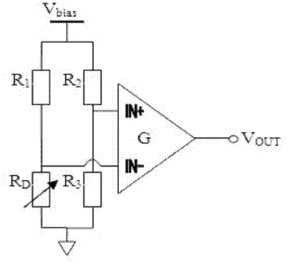
[0042] Such as figure 1 As shown, the detector R D The output signal can be expressed as

[0043] V out = G ( V bias R 3 R 2 + R 3 - V bias R D R 1 + R D )

[0044] where R 1 is the bias resistor on the detection arm, R 2 is the bias resistor on the trim arm, R D is the detector resistance value, R 3 In order to balance the resistance, G is the magnification of the instrume...


PUM


Abstract

The invention provides a mid-infrared detection circuit parameter design method based on a bridge principle. The method comprises the following steps: determining an upper limit and a lower limit of detector operating temperature, a corresponding background voltage allowable value and a maximal signal voltage amplitude allowed by an amplification circuit, determining resistance of a bias resistorand bias voltage of a bridge on a bridge detection arm, and resistance of a bias resistor on a bridge balancing arm, and solving an equation set to obtain a balancing resistance, an amplification multiple and check and correction of an amplification circuit amplification multiple. According to the invention, based on parameters of dark resistance, work voltage and the like of a wide temperature range end point of each detector, optimal solutions of the balancing resistance and the circuit amplification multiple are obtained, and an output signal amplitude and a measurement dynamic range of a bridge type mid-infrared detection circuit are raised. The method has the characteristics of concise step and convenient programming, and can be used for designing balancing resistance and circuit amplification multiple parameters of the mid-infrared detection circuit in quantities.

Description

technical field [0001] The invention relates to a parameter design method of a bridge-based mid-infrared detection circuit, in particular to a parameter design method of an electric bridge detection circuit using a photoconductive type mid-infrared detector to measure mid-infrared laser parameters. Background technique [0002] Photoconductive mid-infrared detectors such as mercury cadmium telluride and indium antimonide usually use such as figure 1 The structure of the bridge plus instrumentation amplifier is shown. R in the figure 1 is the bias resistor on the detection arm, R 2 is the bias resistor on the trim arm, R D is the detector resistance value, R 3 In order to balance the resistance, G is the magnification of the instrumentation amplifier. [0003] Affected by the temperature characteristics of HgCdTe detectors, when the working environment temperature changes, R D It will change monotonously with temperature, and the variation trends of different detectors ...

Claims


Application Information

Patent Timeline
Patent Type & Authority Applications(China)
IPC IPC(8): G01J1/42
Inventor 冯刚王振宝冯国斌杨鹏翎张磊邵碧波陈绍武
Owner NORTHWEST INST OF NUCLEAR TECH
Why Eureka
Try Eureka