Microbiological fuel cell composite material anode and its manufacturing method

A composite material and fuel cell technology, applied in battery electrodes, circuits, electrical components, etc., can solve the problems of low removal rate of organic pollutants, low power generation capacity of microbial fuel cells, etc., to improve the anode electron transfer rate, increase the Electron transfer rate, effect of increasing surface area

Active Publication Date: 2014-07-30
哈尔滨佳泰达微生物燃料电池科技有限公司
View PDF4 Cites 0 Cited by
  • Summary
  • Abstract
  • Description
  • Claims
  • Application Information

AI Technical Summary

Problems solved by technology

[0009] The purpose of the present invention is to solve the problems of low power generation capacity of microbial fuel cells and low removal rate of organic pollutants in water bodies or sediments, and further provide a composite material anode for microbial fuel cells and its manufacturing method

Method used


Image

  • Microbiological fuel cell composite material anode and its manufacturing method
  • Microbiological fuel cell composite material anode and its manufacturing method
  • Microbiological fuel cell composite material anode and its manufacturing method

Examples


specific Embodiment approach 1

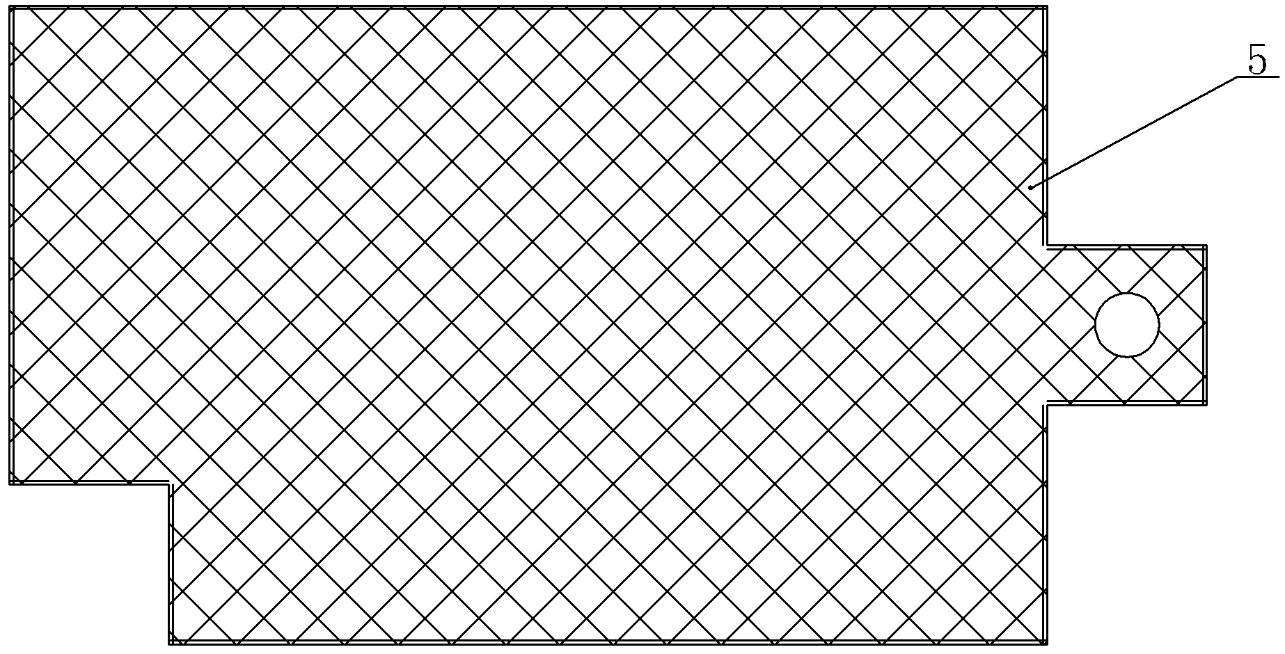
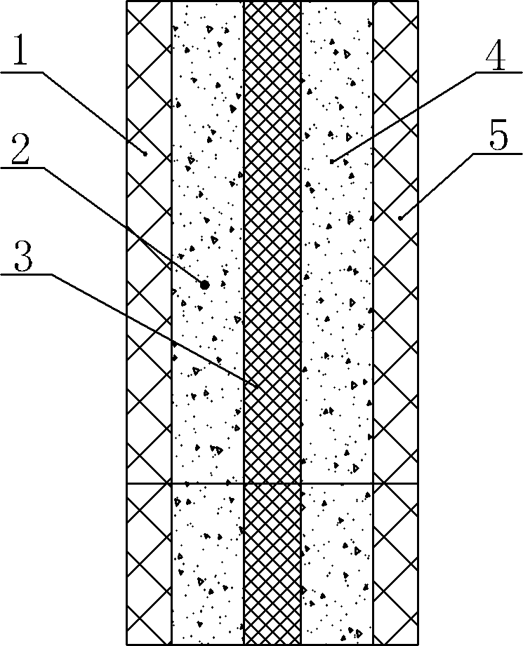
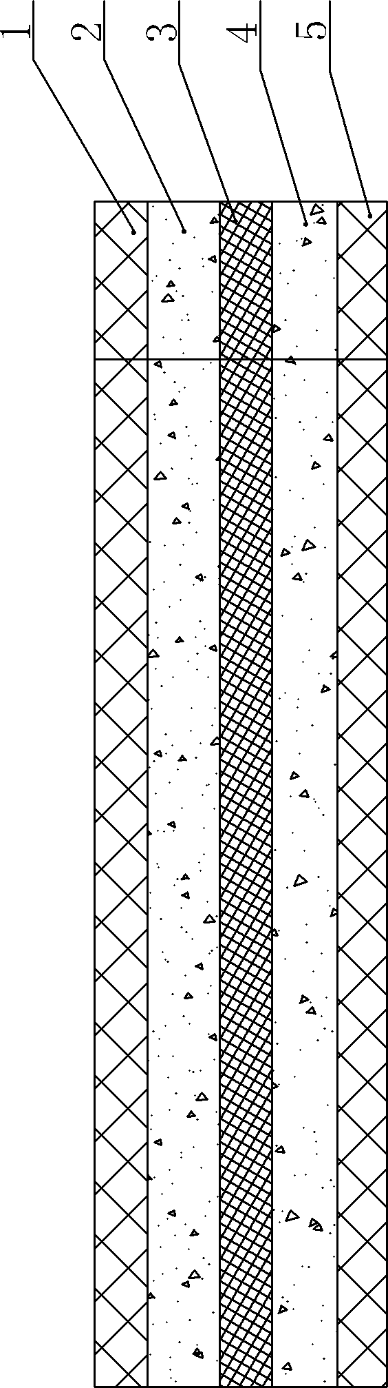
[0019] Specific implementation mode one: combine Figure 1 ~ Figure 3 To illustrate this embodiment, a microbial fuel cell composite material anode of this embodiment is a pressed product, and the anode includes a first wire mesh layer 1, a first non-metallic plate layer 2, a second wire mesh layer 3, The second non-metal plate layer 4 and the third metal mesh layer 5, the second non-metal plate layer 2 is located between the first metal mesh layer 1 and the second metal mesh layer 3, the second non-metal plate layer 4 is set Between the second wire mesh layer 3 and the third wire mesh layer 5, the wires of the first wire mesh layer 1, the second wire mesh layer 3 and the third wire mesh layer 5 are all Nitriding and carburizing composite layers, the materials of the first non-metallic plate layer 4 and the second non-metallic plate layer 5 are carbon-based materials, and the metal mesh of the second metal mesh layer 3 The aperture is smaller than the aperture of the wire mes...

specific Embodiment approach 2

[0021] Specific implementation mode two: combination figure 2 and image 3 To illustrate this embodiment, the second wire mesh layer 3 described in this embodiment is one of a titanium wire mesh layer, a nickel metal mesh layer, a 316 stainless steel wire mesh layer or a 316L stainless steel wire mesh layer. Such setting can effectively improve the anti-corrosion ability of the product, and is suitable for water bodies in different water areas. Others are the same as in the first embodiment.

specific Embodiment approach 3

[0022] Specific implementation mode three: combination figure 2 and image 3 Describe this embodiment, the wire mesh of the second wire mesh layer 3 described in this embodiment is a square hole mesh, the wire diameter of the metal wire of the second wire mesh layer 3 is 0.5~5.0mm, the second metal wire The aperture of the wire mesh of the mesh layer 3 is 3-30mm. Such setting meets the design requirements. Others are the same as in the first or second embodiment.


PUM

PropertyMeasurementUnit
thicknessaaaaaaaaaa
diameteraaaaaaaaaa
pore sizeaaaaaaaaaa

Abstract

The invention provides a microbiological fuel cell composite material anode and a manufacturing method thereof, and relates to a fuel cell composite material anode and a manufacturing method thereof, so that the problems of low electricity generation capacity and low removal rate of organic pollutant in water body or deposit can be solved. The anode is a compressing piece, the anode comprises a first wire mesh layer, a first non-metal sheet layer, a second wire mesh layer, a second non-metal sheet layer and a third wire mesh layer, the second non-metal sheet layer is positioned between the first wire mesh layer and the second wire mesh layer, the second non-metal sheet layer is arranged between the second wire mesh layer and the third wire mesh layer. The main steps for manufacturing the microbiological fuel cell composite material anode comprise: 1) irregularly etching the wire mesh, 2) performing a nitrocementation to liquid phase plasma, 3) compacting the material, 4) performing a carburization to liquid phase plasma, and 5) treating the composite material. The invention is used for power generation of the microbiological fuel cell and the organic pollutant in water body deposit removal.

Description

technical field [0001] The invention relates to a fuel cell composite anode and a manufacturing method thereof. Background technique [0002] At present, many countries in the world are facing serious problems of environmental pollution and energy crisis. With the research and development of global new energy and sustainable energy, research on microbial fuel cells (MFC), especially microbial fuel cells The research and manufacture of anodes and cathodes has become one of the important ways to solve the two major problems of the environment and energy crisis in the world today. As a dual-function MFC technology for treating pollutants and generating electricity, it has attracted widespread attention from various countries. The electricity generation efficiency of microbial fuel cells and the removal rate of organic pollutants are the two major indicators in this field. Most of the research at home and abroad is in the scientific research or experimental stage. No real break...

Claims


Application Information

Patent Timeline
Patent Type & Authority Patents(China)
IPC IPC(8): H01M4/86H01M4/88
CPCY02E60/50
Inventor 韩忠健王英男韩悟冥
Owner 哈尔滨佳泰达微生物燃料电池科技有限公司
Why Eureka
Try Eureka