Field emission illumination light source

A lighting source and emitter technology, applied in the field of field emission lighting sources, can solve the problems of high driving voltage, low utilization rate of anode reflective layer, low luminous efficiency of diode structure and grid structure, etc.

Active Publication Date: 2012-01-25
OCEANS KING LIGHTING SCI&TECH CO LTD +1
View PDF3 Cites 7 Cited by
  • Summary
  • Abstract
  • Description
  • Claims
  • Application Information

AI Technical Summary

Problems solved by technology

The two-pole structure has only two electrodes, the cathode and the anode. The cathode is usually a metal ball and wire structure. As a spherical light source, the shell is usually relatively large, that is, the distance between the cathode and the anode is relatively large, and a relatively high driving voltage is required. On the other hand, if the metal wire is used as the cathode, the utilization rate of the anode reflective layer is not high
It can be seen that the luminous efficiency of the diode structure and the gate structure is not high.

Method used


Image

  • Field emission illumination light source
  • Field emission illumination light source
  • Field emission illumination light source

Examples


Embodiment Construction

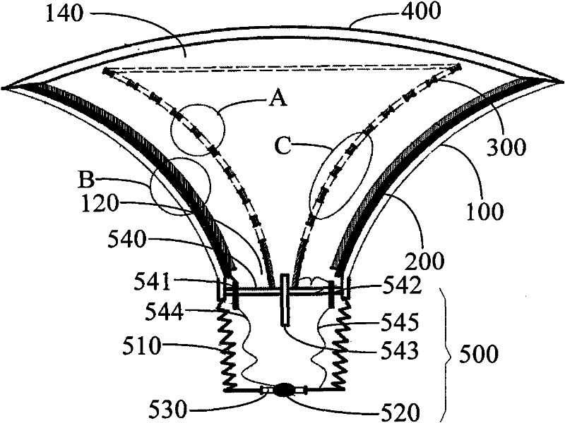
[0021] Such as figure 1 As shown, the field emission lighting source of an embodiment includes a hollow cylindrical housing 100 , an anode 200 , a cathode 300 , a transparent member 400 and a lamp cap 500 . One end of the casing 100 is connected to the lamp cap 500 , and the other end is closed by the transparent member 400 . The anode 200 is arranged in the side wall of the housing 100, the cathode 300 and the anode 200 are both adapted to the shape of the side wall of the housing 100, the cathode 300 is fixed on the lamp holder 500 and is opposite to the anode, and a plurality of light-transmitting holes are opened on the cathode .

[0022] The casing 100 is roughly funnel-shaped. Two ends of the housing 100 are respectively provided with an installation opening 120 and a light outlet 140 . The sidewall of the housing 100 is arc-shaped. The width of the housing 100 gradually increases along the axial direction away from the installation opening 120 , so that the width of...


PUM


Abstract

The invention relates to a field emission illumination light source, which comprises a hollow tubular shell, an anode, a cathode and a lamp cap, wherein one end of the shell is connected with the lamp cap, the anode is arranged in a side wall of the shell, the cathode and the anode are both adaptive to the shape of the side wall of the shell, the cathode is fixed on the lamp cap and is opposite to the anode, and the cathode is provided with a plurality of light holes. In the field emission illumination light source, the shell has the same shape as that of a cathode substrate, the anode is coated on the side wall of the shell, and the cathode is provided with the light holes, so a light emitting area is enlarged, visible light penetrates through the light holes to effectively improve the light emitting effect, and after voltage is applied, the cathode substrate forms an emission source, and emitted electrons impact the anode to emit visible light so as to obtain higher light emitting efficiency. The characteristics of low working voltage, low power consumption and stable emission are realized.

Description

【Technical field】 [0001] The invention relates to an illumination source, in particular to a field emission illumination source. 【Background technique】 [0002] At present, most of the light sources used for daily lighting are fluorescent lamps and LED light sources. The inside of the fluorescent lamp is filled with a mixed gas containing mercury, which uses the discharge of the mixed gas to emit light or the ultraviolet light generated by the discharge of the mixed gas to excite the phosphor to emit light. However, the light generated by this mixed gas discharge light source easily causes visual fatigue and pollutes the environment due to the presence of mercury in the mixed gas. LED light sources also have problems such as self-scattering, rapid life decay when working in a high-temperature environment, and poor light divergence. In addition, due to the limitations of color rendering and color temperature and the characteristics of LED as a point light source, LED light ...

Claims


Application Information

Patent Timeline
Patent Type & Authority Applications(China)
IPC IPC(8): H05B33/02
Inventor 周明杰邵鹏睿马文波
Owner OCEANS KING LIGHTING SCI&TECH CO LTD
Why Eureka
Try Eureka